LED Strip Sample Testing Protocol Before Bulk Orders
- 2026-09-19 13:17
- /
- Arraystar
Never place a bulk LED-strip order on a datasheet and a golden sample alone. Run a short, repeatable sample test protocol: measure actual W/m and current, lm/m and efficacy, CCT/CRI/SDCM, heat on the real aluminum profile, voltage drop over your run length, dimming/flicker, adhesive and (for IP product) ingress resistance, then lock the passing values in the purchase contract with tolerances. A few hours of bench testing prevents container-loads of underperforming or overheating product.
Why Sample Testing Decides the Order
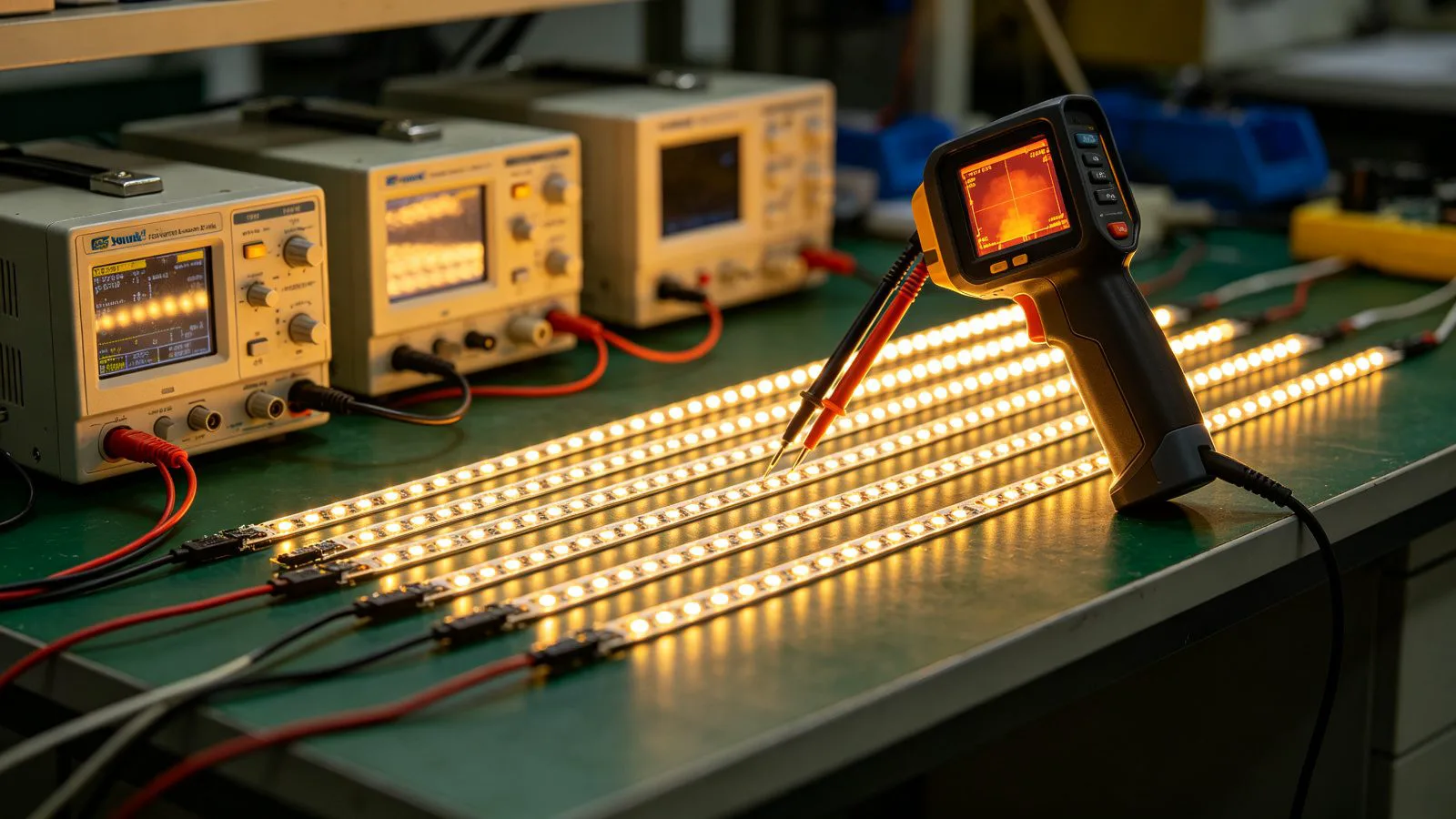
Samples are where marketing claims meet physics. The same nominal specification — say ‘24 V, 14.4 W/m, 3000 K, CRI90’ — can describe strips that differ sharply in real power, brightness, colour, heat and reliability because of LED bin, driver current, PCB copper and build quality. A golden sample that looks good on a desk also tells you nothing about voltage drop on a 15-metre run, temperature after hours in an aluminum channel, or dimming behaviour with your driver. A defined test protocol, applied to the exact product you will buy, converts subjective impressions into pass/fail numbers you can contract against and re-check at incoming inspection.
- Verify real electrical load for driver sizing and safety margin.
- Measure light and colour rather than trusting the label.
- Test thermally installed — loose on a desk runs artificially cool.
- Prove run length and dimming in the real configuration.
- Check mechanical/IP/adhesive fit for the installation.
The Test Protocol, Step by Step
Sample test plan
| Test | Equipment | Pass criterion (example) |
|---|---|---|
| Power / current | Wattmeter / DC clamp, PSU | W/m & A/m within ±10% of spec |
| Light output | Integrating sphere / lux setup | lm/m & lm/W meet agreed values |
| Colour | Spectrometer / colour meter | CCT ±tol, CRI/R9, SDCM bin |
| Thermal | Thermocouple / thermal camera on profile | Tc/Ts within rated, stable |
| Voltage drop | Full run, meter both ends | End voltage & brightness within limit |
| Dimming/flicker | Chosen driver/dimmer, flicker check | Smooth, no flicker/dead travel |
| Adhesion | Real substrate, peel/24 h | Secure bond after cleaning |
| Ingress (IP) | Water test / records for IP product | No intrusion, sealed ends |
Run electrical and thermal tests on the strip mounted in the actual aluminum channel and at the intended density/run length, powered by the same voltage and (where possible) driver family you will deploy. Let it reach thermal equilibrium (typically 30–60 minutes) before recording temperature and hot lumens. For colour, compare samples side by side on white card and to a reference, and check multiple points along and between reels to expose bin mixing.
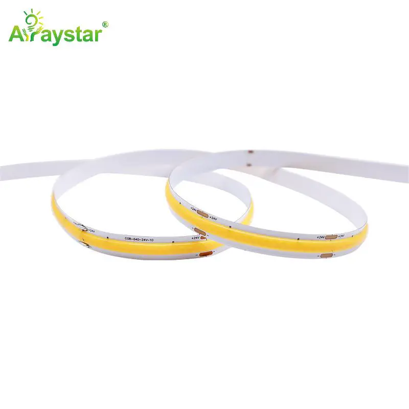
Thermal, Run-Length and Dimming Tests
- Thermal: measure solder-point/Tc and channel temperature at steady state; sustained high temperature predicts short life and colour shift (see our L70 guide).
- Voltage drop: wire the longest planned run, measure voltage at feed and far end, and photograph brightness difference; define an acceptable drop (commonly kept within a few percent) and feed-point spacing.
- Dimming: sweep the exact TRIAC/0–10 V/DALI/PWM control from 100% to minimum; check for flicker, pop-on, drop-out and colour shift at low end (see our flicker guide).
- Power margin: size drivers at ~80% of rated wattage using measured (not nominal) W/m.
- Aging screen: run samples continuously (e.g. 24–72 h) to catch infant failures and observe lumen/colour stability.
Common sample failures and what they mean
| Observation | Likely issue |
|---|---|
| Runs hot on the channel | Over-driven / thin copper / poor PCB |
| End of run dim/pink | Voltage drop, under-sized feed/copper |
| Visible colour patches | Mixed bins / poor binning control |
| Flicker/shimmer when dimmed | Incompatible driver/PWM, poor current |
| Dead LEDs after aging | Solder/LED quality, thermal stress |
| Tape lifts after 24 h | Weak adhesive / poor surface prep |
Turning Results Into a Contract Standard
- Record measured values and keep the approved (sealed) sample as the reference standard.
- Write tolerances into the specification/contract: W/m, lm/m, CCT ±K, SDCM, CRI/R9, dimensions, IP.
- Require batch test data and bin consistency reel-to-reel for mass production.
- Define incoming inspection against the same tests (see our AQL guide) and rejection/rework terms.
- Test accessories together: drivers, dimmers, connectors and profiles as a system, not in isolation.
- For custom products, agree who approves the first article before mass production starts.
Sample sign-off record
| Field | Record |
|---|---|
| SKU / configuration | Exact product, voltage, CCT, CRI, IP |
| Measured W/m, lm/m, lm/W | With equipment and date |
| CCT/CRI/SDCM | Instrument readings |
| Thermal / run / dimming | Steady-state results, run length |
| Approved sample ID | Sealed reference retained |
| Contract tolerances | Acceptance limits for bulk |
We encourage structured sample testing and provide pre-production samples, datasheets and batch photometric/thermal data, and we support specifying the passing values contractually so bulk production matches the approved article. Tell us your application, run lengths and control gear and we will supply samples configured for the exact tests that matter.
Recommended Products
Frequently Asked Questions
What should I test on an LED strip sample before bulk order?
At minimum measure actual W/m and current, lm/m and efficacy, CCT/CRI/SDCM with a colour meter, steady-state temperature mounted in the real aluminum profile, voltage drop and brightness over your longest run, dimming/flicker with the actual driver, plus adhesive and ingress performance for IP product. Run an aging screen (24–72 h) to catch early failures.
How do I test LED strip brightness and colour?
An integrating sphere gives lm/m and lm/W; a handheld spectrometer or colour meter gives CCT, CRI/R9 and SDCM. Compare samples side by side on white card, powered identically, checking several points along each reel and between reels to expose bin mixing. Without instruments, side-by-side comparison to a sealed reference still reveals gross differences.
How long should I run an LED strip sample to test heat?
Mount it in the actual aluminum channel at the planned density and run length, power it at rated voltage and let it reach thermal equilibrium — commonly 30–60 minutes — before recording solder-point/channel temperature. A strip held loosely on a desk for five minutes runs artificially cool and will not predict installed life.
How do I test voltage drop on a long LED strip run?
Wire the longest run you plan at the specified voltage, measure voltage at the feed point and the far end with a multimeter, and visually/photographically compare brightness from start to end. If the end is dim or shifts colour, shorten runs, add feed points, use thicker-copper/48 V product or larger cable. Define an acceptable drop (often a few percent) in the spec.
Should samples include the driver and aluminum profile?
Yes. Test the strip, driver/dimmer, connectors and profile as the system you will actually install: dimming smoothness, flicker, thermal performance and voltage drop all depend on the combination. Approving strip in isolation and pairing it later with an unsuitable driver is a common cause of field problems.
Ordering samples for a project evaluation?
We supply pre-production samples configured to your voltage, run length and control gear, with photometric/thermal data, and support contracting the passing values. Tell us the application and we will prepare samples built for meaningful testing.
Email: info@arraystarled.com | Phone: +86-0755-2103-6746 | WhatsApp: 0086 1581 8514 077
Need to size your power supply? Use our LED Strip Power Calculator to find the right driver in seconds.