1313 Long-Run Neon: 13×13mm, 12W/m, Accessory Fit Guide
- 2026-11-06 16:15
- /
- Arraystar LED
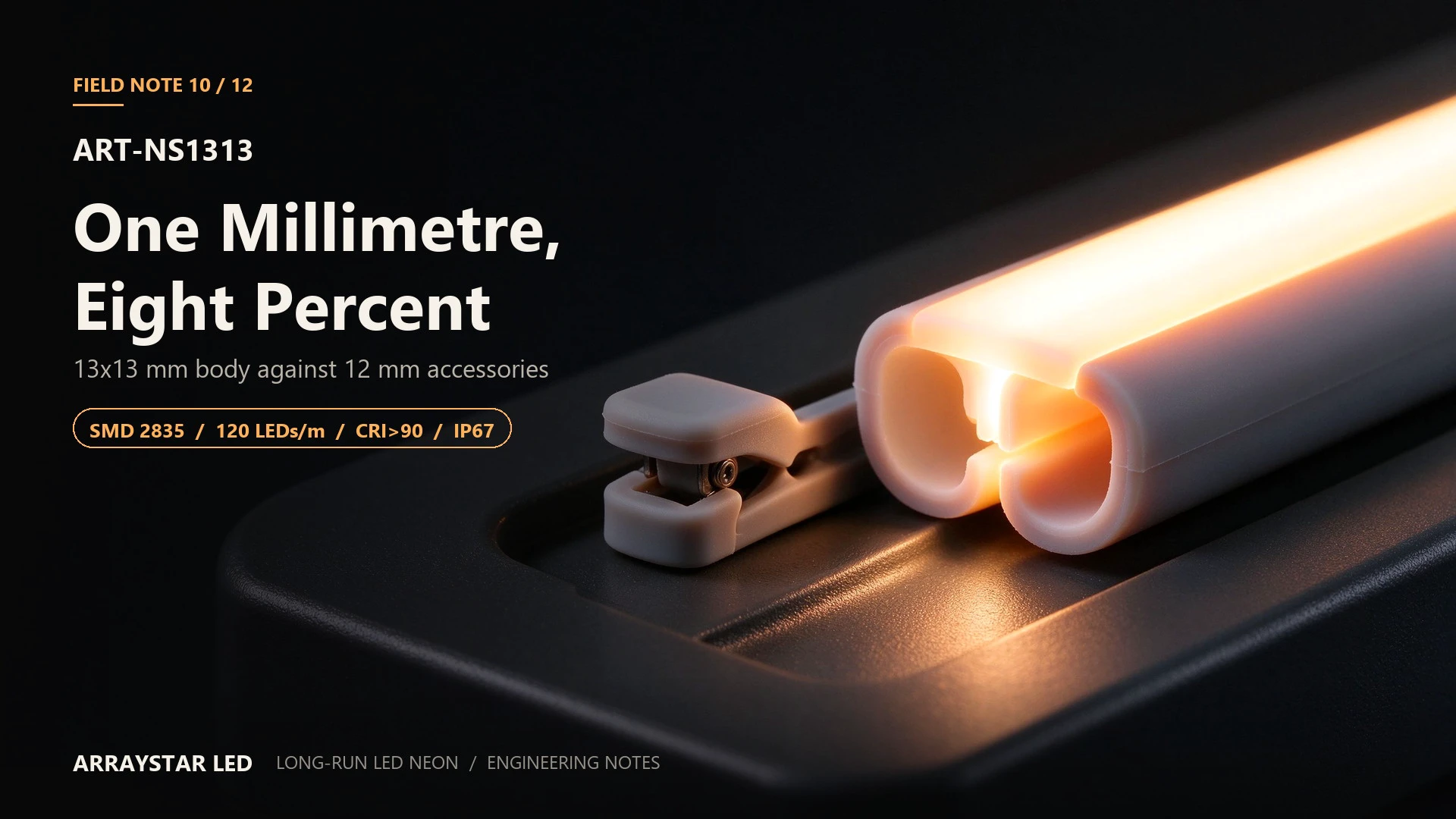
The clip closes, but it does not hold. A 13 × 13 mm body dropped into a detail tooled for 12 × 12 sits loose in the channel, and the installer compensates by adding a second clip or a bead of adhesive. Six months later the body has walked 4 mm along the run, the joint is under tension, and water is at the cap.
A 13 × 13 mm profile exists for a reason: 1 mm more wall thickness on each side gives more material for clamp load, more thermal mass, and a slightly softer line. That extra millimetre also means every 12 mm accessory — clip, channel, end cap, connector — is the wrong size.
1. The accessory mismatch, in numbers
| Component | 12 × 12 accessory | 13 × 13 requirement | Consequence if mismatched |
|---|---|---|---|
| Clip opening | 12 mm | 13 mm | Body slides; clip cannot preload |
| Channel internal width | 12.2–12.5 mm | 13.2–13.5 mm | Body binds or rattles |
| End cap | 12 mm | 13 mm | Cap does not seal the wall |
| Connector body | 12 mm | 13 mm | Strain on the joint, water path |
A 1 mm difference is 8 % of the section width. On a clip that relies on friction and preload, 8 % is the difference between a fixed body and a loose one.
2. Why the extra millimetre is worth specifying
The 13 × 13 body is not a rounding error in the range. Compared with 12 × 12 at the same 12 W/m:
- Wall thickness: more silicone between the PCB and the outside, which distributes clamp load and reduces the bright band under a clip.
- Thermal mass: a larger section holds more heat capacity, so the surface temperature swings less between on and off.
- Optical face: 13 mm against an 8.33 mm pitch gives a slightly softer line than 12 mm — useful where the detail should read as glow rather than edge.
The cost is that the body is 1 mm larger in every direction, and that has to be designed into the detail, not adjusted on site.
3. Optical behaviour
120 × SMD 2835 per metre at 8.33 mm pitch behind a 13 mm diffused face. The face is wider than the pitch by a comfortable margin, so the line is continuous from about 150 mm outward.
- Line width: reads at roughly 13–15 mm at close range.
- Edge softness: slightly softer than the 12 mm body at the same distance, because the diffuser is wider.
- Colour: 1800 / 2700 / 3000 / 4000 / 6000 K, CRI >90. Keep adjacent rolls in the same bin lot.
If the design intent is a crisp architectural edge, the 12 × 12 body is the better fit. If it is a softer neon glow at a similar scale, the 13 × 13 is the more comfortable line.
4. Electrical: 12 W/m, 24 V and 36 V
| Supply | Current per metre | 5 m segment | 10 m load |
|---|---|---|---|
| 24 V | 0.500 A/m | 2.50 A / 60 W | 120 W / 5.0 A |
| 36 V | 0.333 A/m | 1.67 A / 60 W | 120 W / 3.3 A |
Standard long-run practice: 5 m per feed at 24 V, 0.75 mm² conductor minimum, driver at total wattage plus 20–25 % headroom. The 36 V variant reduces current by one third and extends the interval; confirm the exact model before designing around it.
Cut at marked points: 50 mm, six LEDs at 120 LEDs/m.
Feed drop at the segment current (5 m out + 5 m back):
| Conductor | Loop resistance | Drop at the segment | % of supply |
|---|---|---|---|
| 0.50 mm² | 0.37 Ω | 0.93 V | 3.9 % |
| 0.75 mm² | 0.25 Ω | 0.63 V | 2.6 % |
| 1.00 mm² | 0.18 Ω | 0.45 V | 1.9 % |
Use 0.75 mm² as the floor; step up to 1.00 mm² where the driver sits more than 5 m from the first tap.
5. Thermal: 52 mm perimeter
The 13 × 13 section has 52 mm of perimeter, between the 12 × 12 (48 mm) and the 12 × 20 (64 mm). At 12 W/m expect roughly 13–17 K rise above ambient in free air.
The extra wall thickness matters more than the perimeter number: a thicker wall spreads a local hot spot before it reaches the diffuser, which is why a 13 × 13 body shows less clip banding than a 12 × 12 at the same load.
6. Installation: buy the accessory set with the body
The single rule for this SKU: order clips, channel, end caps and connectors as a 13 mm set. Do not assume a 12 mm accessory will "close enough."
- Clips: 200 mm on straights, 100 mm through bends, offset by half a pitch.
- Channel: internal width 13.2–13.5 mm; a 12 mm channel will bind the body and prevent thermal expansion.
- End caps: 13 mm moulded cap, potted joint outdoors.
- Bending: form on a template; the thicker wall accepts a slightly larger minimum radius than a 12 mm body, not a smaller one.
- Cutting: marked points only, 50 mm intervals.
7. Commissioning checks
| Check | Method | Pass criterion |
|---|---|---|
| Clip preload | Try to move the body by hand at a clip | No movement, no silicone compression |
| Cap seal | Visual + continuity | Cap fully seated on the 13 mm wall |
| Feed drop | Head and tail under load | ≤ 3 % of supply |
| Surface temperature | IR probe after 60 min | ≤ 45 °C in still air |
| Line continuity | View at design distance | No ripple, no clip band |
8. Engineering FAQ
Can I use 12 × 12 clips on a 13 × 13 body?
No. The clip cannot preload a body 1 mm wider; it will either not close or close on the diffuser and compress it. Order the 13 mm accessory set with the body.
Why choose 13 × 13 over 12 × 12 at the same wattage?
More wall thickness and thermal mass, a slightly softer line, and less clip banding. Choose it where the body is clamped hard or the detail reads as glow. Choose 12 × 12 where the detail is a crisp edge and the accessory range is standardised.
Does the 1 mm change the minimum bend radius?
Yes, in the direction most installers do not expect: the thicker wall needs a slightly larger radius, not a tighter one. Confirm the batch datasheet before templating a corner.
9. Specification summary
| Parameter | Value |
|---|---|
| Model | ART-NS1313 |
| Cross-section | 13 × 13 mm |
| LED | SMD 2835, 120 LEDs/m |
| Input | 24 V DC / 36 V DC |
| Power | 12 W/m |
| CRI | >90 |
| Colour | 1800 / 2700 / 3000 / 4000 / 6000 K |
| Cut unit | 50 mm (6 LEDs) |
| Warranty | 3 years |
Using a 13 mm body in a 12 mm detail? Send the section and the accessory list. We will confirm which parts must change before the first clip is fixed.