How to Solder LED Strip Connections: Step-by-Step Professional Tutorial
- 2026-09-09 15:56
- /
- Arraystar
Quick Answer
Soldering is the most reliable method for connecting LED strips, providing better electrical contact, lower resistance, and greater durability than snap-on connectors. To solder LED strips: 1) Cut at marked copper pads, 2) Tin pads with solder, 3) Strip and tin wire ends, 4) Heat pad and wire together while applying solder, 5) Insulate with heat shrink tubing. Use 30-60W soldering iron with fine tip, rosin-core solder (60/40 or 63/37), and always match polarity (+ to +, - to -). For permanent, outdoor, or professional installations, soldering is strongly recommended.
Why Solder Instead of Connectors?
While snap-on connectors are quick and convenient, soldering provides significant advantages for permanent installations: Better electrical contact (lower resistance = less voltage drop and heat), greater durability (won't come loose from vibration or temperature changes), waterproof capability (can be properly sealed with heat shrink), lower cost (no expensive connectors needed), and more flexible (can connect any wire gauge or type). For professional, permanent, or outdoor installations, soldering is strongly recommended. Connectors are fine for temporary installations, DIY projects, or situations where soldering is not practical. Soldering is a skill that can be learned with practice, and the results are well worth the effort for reliable, long-lasting LED strip installations.
Tools and Materials Needed
1) Soldering iron: 30-60W adjustable temperature iron with a fine chisel or conical tip. Set temperature to 300-350°C (570-660°F). A temperature-controlled iron is highly recommended for consistent results. 2) Solder: Rosin-core solder, 60/40 (tin/lead) or 63/37 for best flow and lower melting point. Lead-free solder (SAC305) works but requires higher temperature (350-400°C) and is more difficult for beginners. Use 0.5mm-1.0mm diameter solder for LED strip work. 3) Wire: 20-22 AWG solid or stranded wire for power connections. Use red for positive (+), black/white for negative (-). For RGB strips, use 4-conductor wire (red, green, blue, black/common). Silicone wire is flexible and heat-resistant. 4) Heat shrink tubing: 3:1 ratio heat shrink with adhesive for waterproof seals. Choose size that fits snugly over the connection (typically 3-5mm diameter for LED strip connections). 5) Additional tools: Wire strippers (for removing wire insulation), flush cutters (for cutting wire and trimming solder), helping hands (third hand with clips to hold work), isopropyl alcohol (90%+) and brush (for cleaning flux residue), heat gun or lighter (for shrinking heat shrink), safety glasses (to protect eyes from solder splatter), and ventilation (to avoid inhaling solder fumes). 6) Optional: Desoldering pump or solder wick (for removing mistakes), magnifying glass or microscope (for detailed work), fume extractor (for solder smoke), and anti-static wrist strap (for sensitive electronics, though LED strips are generally ESD-tolerant).
Step-by-Step Soldering Process
Step 1: Preparation. Cut the LED strip at the marked copper pad points using sharp scissors or a utility knife. Ensure a clean, straight cut through the copper pads (not between pads). Strip 5-8mm of insulation from wire ends using wire strippers. Plug in the soldering iron and let it heat up (3-5 minutes). Clean the iron tip by wiping on damp sponge or brass wire cleaner. Step 2: Tin the pads. Apply a small amount of solder to the tip of the iron (tin the tip—this improves heat transfer). Touch the iron tip to the copper pad on the LED strip while feeding a small amount of solder from the opposite side. Create a small, shiny mound of solder on each pad. Don't apply too much—just enough to cover the pad with a thin layer. If solder doesn't flow easily, the pad may be dirty or oxidized—clean with isopropyl alcohol. Step 3: Tin the wires. Heat the stripped wire end with the iron while applying solder. Ensure the solder flows evenly through the wire strands, creating a shiny, tinned end. Let cool. Tinning wires makes them easier to solder and prevents fraying. Step 4: Solder the connection. Place the tinned wire onto the tinned pad. Heat both simultaneously with the iron tip for 2-3 seconds. The solder should flow and merge, creating a shiny, smooth connection. Remove the iron and hold the wire still for 3-5 seconds while the solder cools and solidifies. Do not move the wire while cooling—this creates a cold solder joint (dull, grainy appearance, weak connection). Step 5: Inspect and insulate. Check the connection: it should be shiny, smooth, and well-formed (like a small volcano or Hershey's kiss). No solder bridges between adjacent pads (can cause short circuits). No cold joints (dull, grainy, crystalline). Clean flux residue with isopropyl alcohol and a small brush. Slide heat shrink tubing over the connection and heat with a heat gun (or lighter, carefully) until it shrinks tightly and adhesive flows out from ends. For outdoor/waterproof applications, use adhesive-lined heat shrink and ensure complete coverage of all exposed metal. Step 6: Test. After all connections are made and insulated, connect power and verify all sections light up correctly. Check for even brightness, correct colors (for RGB), and no flickering. If a section doesn't light, check polarity and connections. If brightness is uneven, check for cold joints or voltage drop.
Common Soldering Mistakes and How to Fix Them
1) Cold joints: Caused by moving the wire before solder cools, insufficient heat, or dirty surfaces. Appearance: dull, grainy, crystalline, or rough. Fix: Reheat the joint with iron until solder flows smoothly, then let cool without moving. Add a small amount of fresh solder if needed. 2) Too much solder: Creates blobs that can bridge adjacent pads, causing short circuits. Also creates weak, unreliable connections. Fix: Use solder wick (braided copper) to remove excess solder by heating wick over joint—solder will be absorbed into wick. Then re-solder with less solder. 3) Solder bridges: Solder connecting two adjacent pads, causing a short circuit. This is a common mistake with closely spaced pads (RGB strips). Fix: Use solder wick or desoldering pump to remove the bridge. Drag a hot iron tip between pads to separate solder. Use a utility knife to carefully cut through bridge if other methods fail. 4) Lifted pads: Caused by excessive heat (too long or too hot), excessive force, or repeated soldering/desoldering. The copper pad lifts off the PCB substrate. Fix: Carefully scrape the PCB trace beyond the pad to expose fresh copper, then solder directly to the trace. Or use the next available pad on the strip. Prevention: Use proper temperature (300-350°C), limit heating to 2-3 seconds per joint, and don't apply force. 5) Burnt/damaged LEDs: Caused by too much heat for too long, or the iron tip touching the LED itself. LEDs can be damaged by excessive heat. Fix: Cut out the damaged LED section and replace with a new section, or bridge the gap. Prevention: Work quickly (2-3 seconds per joint), use a fine tip, avoid touching LEDs directly, and use temperature-controlled iron. 6) Polarity reversal: Connecting + to - and - to +. The strip won't light up (but usually won't be damaged—LEDs are reverse-voltage tolerant up to a point). Fix: Double-check polarity before soldering. Match + to + (red wire), - to - (black/white wire). For RGB strips, match R/G/B labels and common (+ or -). 7) Insufficient heat: If iron is not hot enough or contact time too short, solder won't flow properly, creating weak, grainy joints. Fix: Ensure iron is properly heated (300-350°C), clean tip, and apply heat for 2-3 seconds. 8) Flux residue: Rosin flux residue can be sticky and attract dust, and may be slightly conductive in humid environments. Fix: Clean all joints with isopropyl alcohol (90%+) and a small brush after soldering. 9) Wrong solder type: Using acid-core solder (for plumbing) instead of rosin-core (for electronics) can damage components and cause corrosion. Fix: Always use rosin-core solder for electronics. If acid-core was used, clean thoroughly with isopropyl alcohol. 10) Burned fingers: Touching hot iron or freshly soldered joints. Fix: Use helping hands to hold work, wait for joints to cool before touching, and use heat-resistant gloves if needed.
Soldering vs Connectors Comparison Table
| Factor | Option A | Option B |
|---|---|---|
| Brightness | Medium-High | High |
| Efficiency | Good | Excellent |
| Cost | Lower | Higher |
| Best For | General applications | Premium installations |
Recommended Products
Hidden Touch Sensor Switch (Non-Contact / Through-Panel Type)
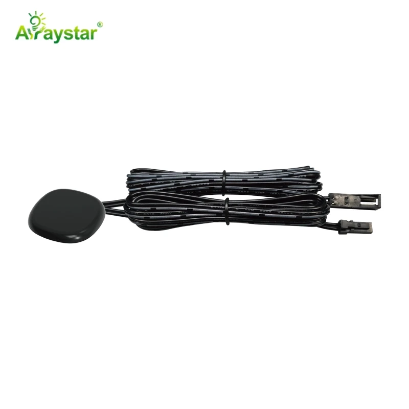
Professional led strip control system from Arraystar LED, manufactured with premium quality components and backed by our 3-year warranty.
ART-NT1616(7)
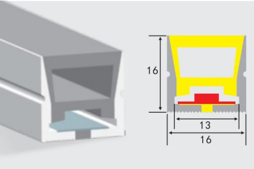
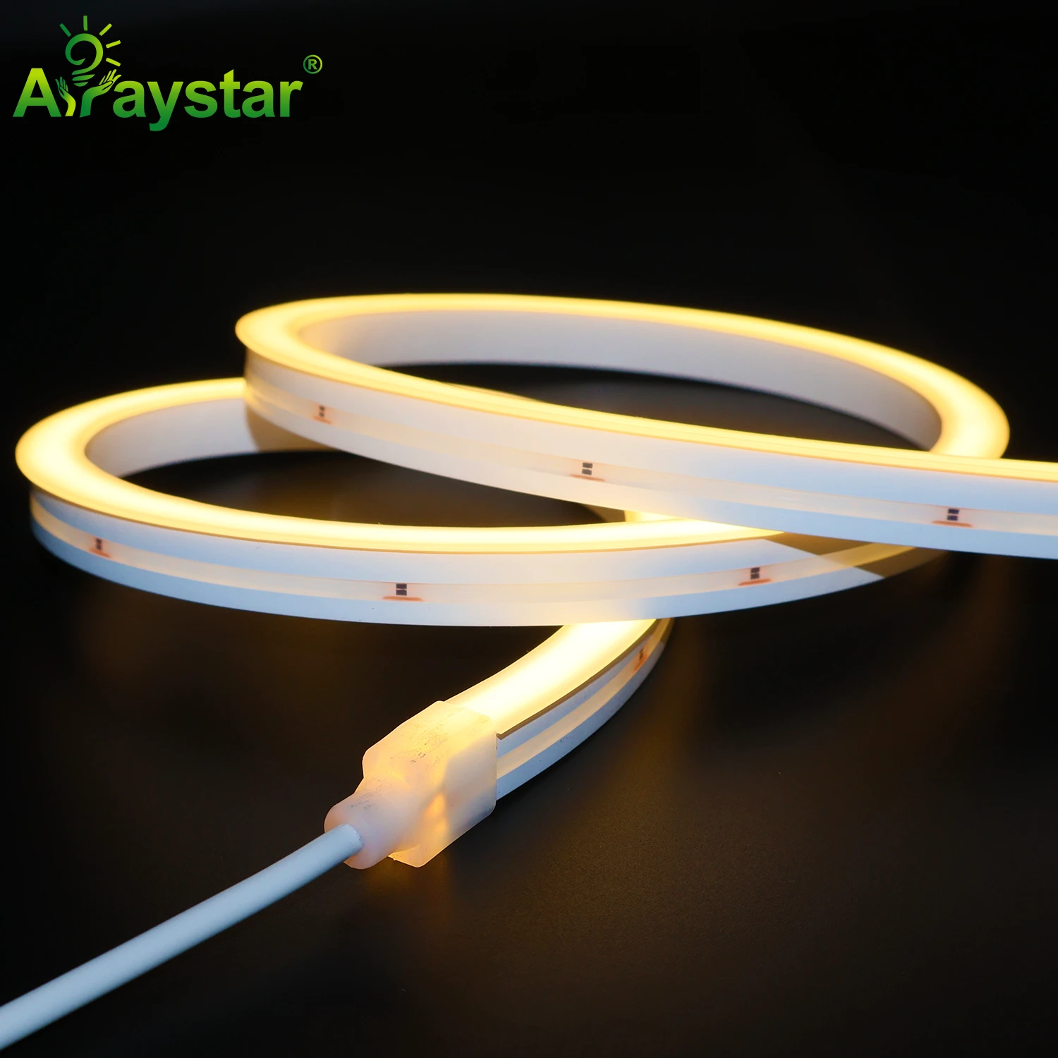
Professional built-in pet sheet neon tube from Arraystar LED, manufactured with premium quality components and backed by our 3-year warranty.
Frequently Asked Questions
Q: Can led strip control system be used outdoors?
A: Only IP65 or higher rated strips are suitable for outdoor use. IP65 for covered/splash areas, IP67 for exposed outdoor, IP68 for underwater/submersion. Always use waterproof connectors and properly seal all connections for outdoor installations.
Q: How do I dim led strip control system?
A: Multiple dimming options available: 0-10V, PWM, TRIAC, DALI, DMX512, and wireless (WiFi/Zigbee/Bluetooth). Ensure your dimmer is compatible with the strip's voltage and current. COB strips dim especially smoothly due to uniform light output.
Q: What is the maximum run length for led strip control system?
A: This depends on voltage and copper weight. 12V strips typically max 5m, 24V up to 10m, 48V up to 20m. For longer runs, use power injection at both ends or intermediate points to prevent voltage drop and color shift.
Q: What should I consider before buying led strip control system?
A: Key factors include: required brightness (lumens/m), color temperature, voltage (12V/24V/48V), IP rating for environment, LED density, CRI requirement, dimming compatibility, and total run length. Calculate total wattage to size your power supply correctly.
Q: How do I calculate the power supply size for led strip control system?
A: Multiply the strip's wattage per meter by total length, then add 20% headroom. For example: 5m × 14.4W/m = 72W + 20% = 86.4W, so choose a 100W power supply. Always use a power supply rated for LED applications.
Conclusion
Soldering is the most reliable method for connecting LED strips, providing better electrical contact, lower resistance, and greater durability than snap-on connectors. To solder LED strips: 1) Cut at marked copper pads, 2) Tin pads with solder, 3) Strip and tin wire ends, 4) Heat pad and wire together while applying solder, 5) Insulate with heat shrink tubing. Use 30-60W soldering iron with fine tip, rosin-core solder (60/40 or 63/37), and always match polarity (+ to +, - to -). For permanent, outdoor, or professional installations, soldering is strongly recommended. Arraystar LED offers 15+ years of LED strip manufacturing experience with full OEM/ODM capabilities, CE/RoHS/ERP certification, and 3-year warranty. Contact our team for a free consultation and custom quote for your project.
Ready to start your project? Contact us today for expert guidance and competitive pricing.
About the Manufacturer
ArrayStar LED is a professional LED strip manufacturer in Shenzhen, China since 2010, serving 80+ countries. We support custom OEM/ODM projects (custom CCT, CRI, PCB, logo, packaging) and wholesale supply for distributors and contractors worldwide.