0612B Long-Run Neon: 12W/m, 24V and the Feed-Interval Rule
- 2026-11-06 16:15
- /
- Arraystar LED
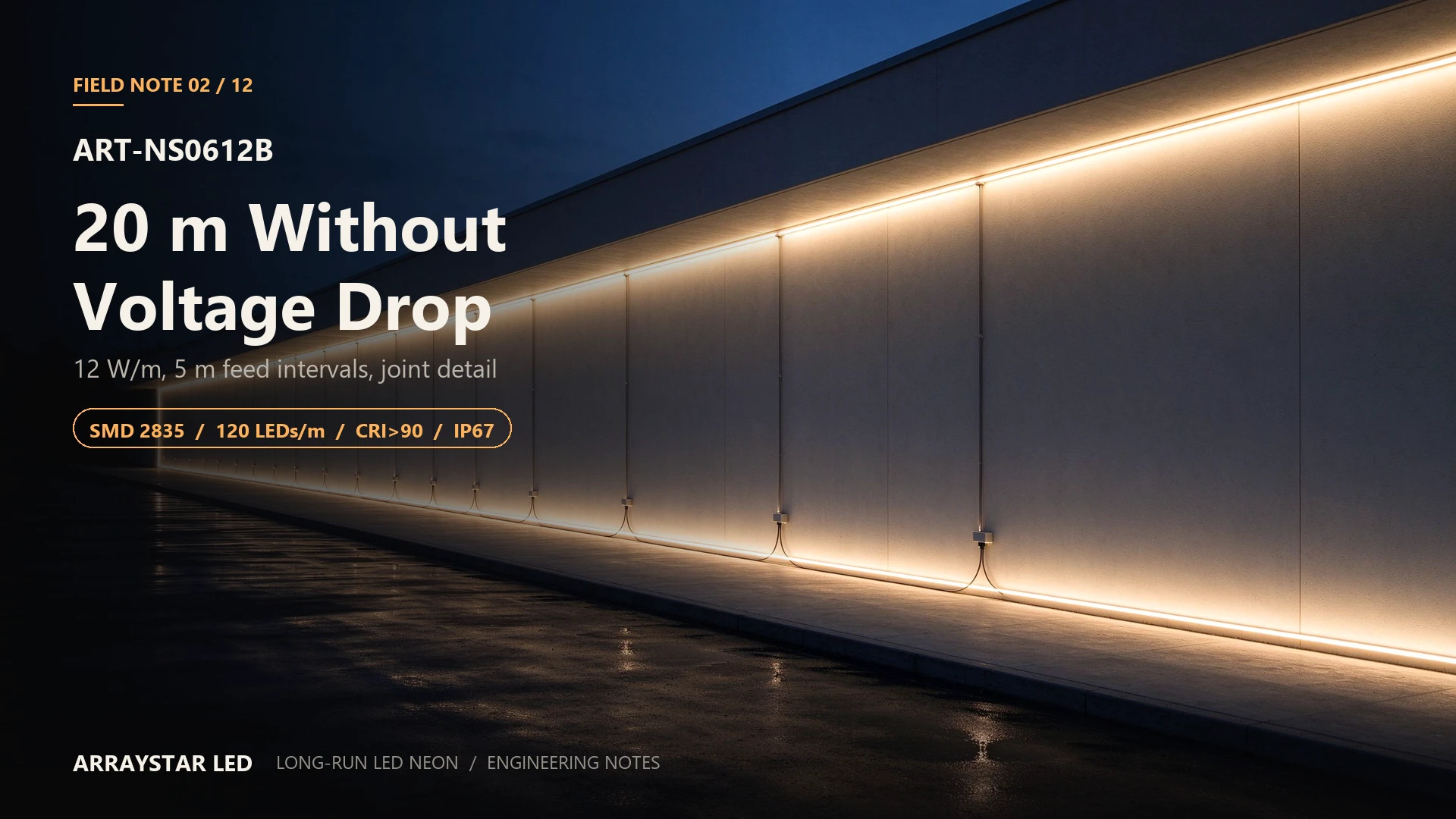
The complaint is almost always phrased as a colour problem: "the last two metres are warmer than the rest." On a 20 m outline it is not a colour problem. It is a current problem. The tail is running at a lower voltage than the head, the white die is under-driven, and the eye reads the drop as a shift in CCT.
On a 24 V constant-voltage strip, the tail is a voltage divider. The only question is where you place the taps.
1. Why "long run" does not mean "one feed"
At 12 W/m, this body draws 0.50 A per metre at 24 V. A 20 m outline is 240 W and 10 A — and every metre of that run sits behind the track resistance of every metre before it. The voltage at metre 20 is the supply voltage minus the accumulated drop through the strip's own copper.
Two separate resistances are at work:
1. The strip's internal track. Fixed by the manufacturer. This is why the product is specified with a feed interval rather than a single maximum length.
2. The feed cable between driver and strip. Under your control. This is where a wrong conductor size turns a 3 % drop into 5 %.
The installation manual for this model recommends re-feeding roughly every 5 m, and accepting up to 10 m only where a slight tolerance at the tail is acceptable. That is not a conservative suggestion — it is the point where the accumulated track drop stays inside the range the eye will not read on white.
2. Planning the electrical segments before the mechanical layout
The mistake is to design the outline as one continuous line and then look for places to hide power feeds. Reverse it: divide the outline into electrical segments of 5 m, then design the mechanical run to match.
| Outline length | Segments | Feed points | Driver load at 24 V |
|---|---|---|---|
| 10 m | 2 × 5 m | 2 | 120 W / 5.0 A |
| 15 m | 3 × 5 m | 3 | 180 W / 7.5 A |
| 20 m | 4 × 5 m | 4 | 240 W / 10.0 A |
| 25 m | 5 × 5 m | 5 | 300 W / 12.5 A |
Size the driver at the total connected wattage plus 20–25 % headroom. For 20 m that is a 300 W unit, not a 240 W unit. A driver loaded to its nameplate will sag at switch-on and dim the first segment of every run.
At 2.5 A per 5 m segment, with the feed pair counted as a round trip:
| Feed conductor | Loop resistance (5 m out + 5 m back) | Drop at 2.5 A | % of 24 V |
|---|---|---|---|
| 0.50 mm² | ≈ 0.37 Ω | ≈ 0.92 V | 3.8 % |
| 0.75 mm² | ≈ 0.25 Ω | ≈ 0.62 V | 2.6 % |
| 1.00 mm² | ≈ 0.18 Ω | ≈ 0.46 V | 1.9 % |
Use 0.75 mm² as the floor per segment. If the driver sits more than 5 m from the first tap, step up to 1.00 mm² or run a dedicated feed pair per segment rather than a shared bus.
3. Where the feeds go, and how to keep them invisible
On a façade outline, the feed points are the only visible compromise. Four rules that hold in the field:
- Put every tap on a vertical face, never on the top or bottom of a horizontal run. Water collects on horizontal surfaces, and a feed entry is the first place it finds.
- Group taps at clip positions. A feed entry hidden behind a mounting clip is invisible from 2 m; a free-hanging cable gland is not.
- Run the return conductor with the feed. If the driver is remote, a two-core feed per segment is cheaper than guessing at the drop later.
- Keep the tap off the lit face. Enter from the back or the side, never through the diffuser.
For a two-end feed on a single length, the tail entry must be sealed exactly like a cut end: moulded cap, potted joint, no adhesive-only seal.
4. The joint detail that decides whether 20 m looks like one line
Electrically, four 5 m segments are four circuits. Optically, they must read as one line. Three things control that:
Bin lot. Keep all rolls for one elevation from the same bin. A 0612 body has a narrow diffuser; a bin step at a joint is visible at 300 mm even when the electrical drop is zero.
Joint alignment. The diffuser faces must be aligned within the wall thickness, not just butted. A 0.3 mm step at the joint reads as a dark notch under grazing light.
Joint placement. Put joints at clip positions and on a straight section, never on a curve. A joint on a radius will open under thermal cycling.
5. Thermal: 12 W/m in a 6 mm body
The 0612B runs 12 W/m — 20 % more than the 10 W/m 0612 — in the same 6 × 12 section. That extra 2 W/m matters because the surface area did not change.
- In free air, expect a surface rise in the region of 15–20 K above ambient.
- In a closed slot with no substrate contact, that rise climbs further and the diffuser yellows from the inside.
Mount this body against a metal channel, or vent the slot at both ends. Do not bury a 12 W/m 0612B run in an unvented plaster reveal and expect a 3-year life at full output.
6. Installation sequence that avoids rework
1. Measure the outline and divide by 5 m. Mark the tap positions on the drawing before any cable is pulled.
2. Confirm driver location and voltage at the first tap under full load, not open circuit.
3. Fix the channel and clips at 150–200 mm centres; leave the tap positions accessible.
4. Cut only at the marked 50 mm points (six LEDs at 120 LEDs/m, 24 V).
5. Seal every cut end and every tap with a moulded cap and potted joint.
6. Commission with a meter, not the eye: head and tail voltage, then a white-flat check at the design viewing distance.
7. Engineering FAQ
Can I run 20 m from a single 24 V feed if I use a bigger cable?
No. The feed cable is only half the resistance; the strip's internal track is the other half and it is fixed. A larger cable reduces the cable term but cannot fix the accumulated track drop. Split the run into 5 m segments.
Does 36 V help on this body?
The 0612B is specified at 24 V DC. Where a 36 V variant is available in the Long Run range, the current for the same wattage drops by one third, which extends the practical feed interval. Confirm the exact model and driver before designing around 36 V.
How do I hide four feed points on a visible façade?
Group them behind clip positions on vertical faces, or bring all taps back to a single concealed junction box at the base of the elevation and feed each segment from there. The second option costs more cable but leaves the elevation clean.
8. Specification summary
| Parameter | Value |
|---|---|
| Model | ART-NS0612B |
| Cross-section | 6 × 12 mm |
| LED | SMD 2835, 120 LEDs/m |
| Input | 24 V DC |
| Power | 12 W/m |
| CRI | >90 |
| Colour | 2700 / 3000 / 4000 / 6500 K |
| Feed interval | ≈ 5 m recommended, 10 m maximum with tolerance |
| Cut unit | 50 mm (6 LEDs) |
| Warranty | 3 years |
Planning an outline longer than 10 m? Send the drawing and the driver location. We will return a segment map with tap positions and a conductor schedule for this body.