1010 Long-Run Neon: 10×10mm, 10W/m, Corner Detailing
- 2026-11-06 16:15
- /
- Arraystar LED
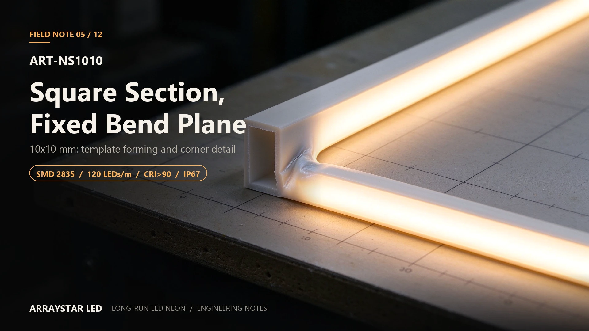
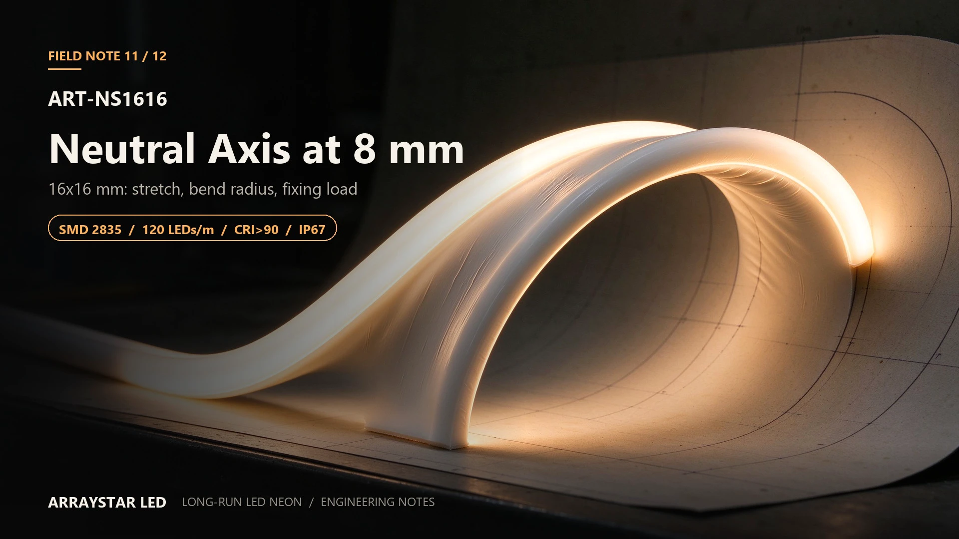
The crease appears on the inside of the corner first. A 10 × 10 mm square body is pulled around a 90° turn by hand, the inner wall compresses, and the silicone folds into a thin white line that no amount of cleaning removes. The outer wall looks fine. The damage is entirely on the side nobody inspects.
A square section is not a round section with corners. It has four flat walls, a defined bend plane, and a neutral axis that sits in the middle of the profile. Bend it in the wrong plane, or to a radius tighter than the wall can absorb, and the failure is built in at installation.
1. What a square section does differently
| Property | Round/oval body | 10 × 10 square body |
|---|---|---|
| Bend behaviour | Smooth in any plane | Defined plane only |
| Inner wall at a corner | Gradual compression | Concentrated crease |
| Emitting face | Curved, soft edge | Flat, crisp edge |
| Fixing | Clip bears on a curve | Clip bears on a flat face |
| Appearance | Neon-like | Architectural line |
The flat face is the reason to choose this body: a 10 mm square gives a crisp, uniform line with a defined edge, which is what a reveal detail or a sign border usually wants. The cost is that the body must be formed, not forced.
2. Bending geometry: where the crease comes from
At a bend, the inner wall travels a shorter path than the outer wall. For a 10 mm section on an inner radius R, the inner wall compression is proportional to the wall thickness divided by the radius. Two practical consequences:
- The minimum radius is set by the wall, not by the LED pitch. A 10 mm square body will not take the radius a 5 mm round body accepts. Confirm the batch datasheet before templating.
- The bend plane is fixed. Bending across the diagonal, or twisting the body through a corner, puts stress on two walls at once and produces a crease even at a generous radius.
Field rule: form every corner on a template — a piece of the actual channel, a plywood jig, or a pre-bent aluminium profile — and leave it for 24 hours before fixing. Hand-forming around a building corner is the single most common cause of a crease.
3. Optical: 10 mm face over an 8.33 mm pitch
120 × SMD 2835 per metre gives an 8.33 mm emitter pitch. A 10 mm diffused face is wider than the pitch, which is why this body reads as a clean line with no visible dot structure at normal viewing distance.
- Viewing distance: continuous from about 200 mm outward. Closer than that, a faint texture is visible on white.
- Edge definition: the flat face produces a sharper edge than an oval body. On a dark surface this reads as a precise architectural line; on a textured surface it can read as a hard edge, which is a design decision, not a defect.
- Colour: 1800 / 2700 / 3000 / 4000 / 6000 K, CRI >90. Keep adjacent rolls in the same bin lot; the flat face shows a bin step more than a curved diffuser would.
4. Electrical: 10 W/m, 24 V or 36 V
| Supply | Current per metre | 5 m segment | Driver (with 20 % headroom) |
|---|---|---|---|
| 24 V | 0.417 A/m | 2.08 A / 50 W | 60 W |
| 36 V | 0.278 A/m | 1.39 A / 50 W | 60 W |
The 36 V version extends the practical feed interval because the current is one third lower for the same wattage. On a long outline, that can remove one or two taps. Do not mix voltages on one driver, and confirm the exact 36 V model before designing the segment plan.
Cut only at the marked points: 50 mm, six LEDs at 120 LEDs/m.
Feed drop at the segment current (5 m out + 5 m back):
| Conductor | Loop resistance | Drop at the segment | % of supply |
|---|---|---|---|
| 0.50 mm² | 0.37 Ω | 0.77 V | 3.2 % |
| 0.75 mm² | 0.25 Ω | 0.52 V | 2.2 % |
| 1.00 mm² | 0.18 Ω | 0.37 V | 1.6 % |
Use 0.75 mm² as the floor; step up to 1.00 mm² where the driver sits more than 5 m from the first tap.
5. Thermal: 40 mm perimeter at 10 W/m
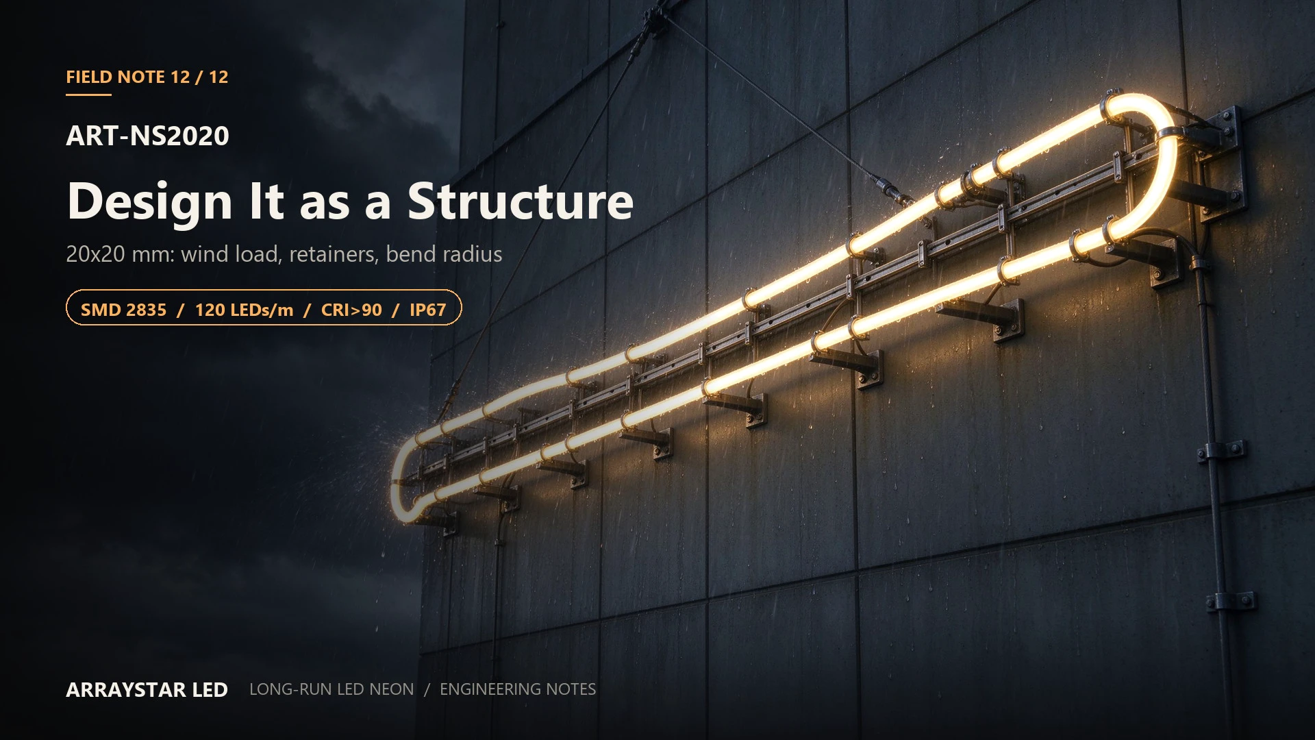
The 10 × 10 section has 40 mm of perimeter, the same as the 8 × 12. At 10 W/m it runs in the same thermal band: expect roughly 13–17 K rise above ambient in free air. In a closed slot, the perimeter is the only path to the substrate — mount against a metal channel or vent the slot at both ends.
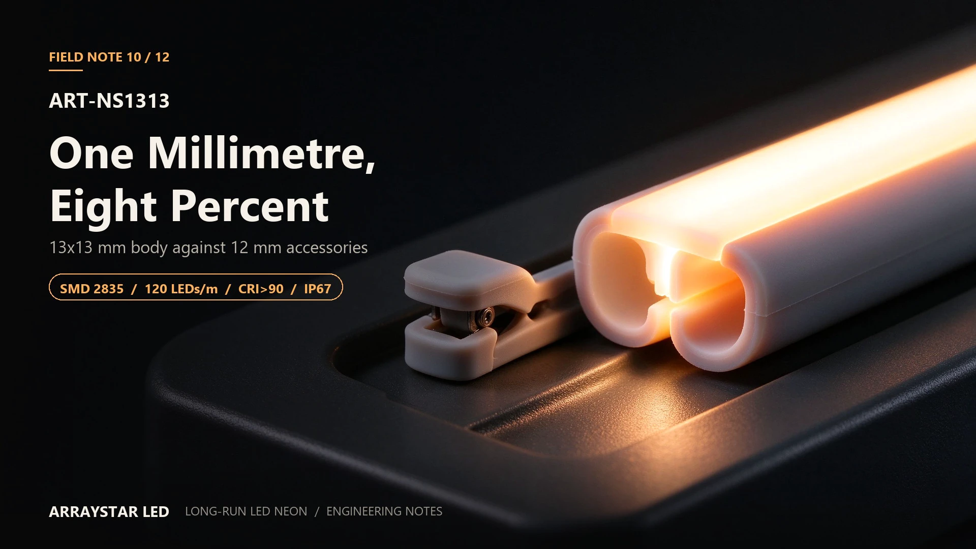
One square-section advantage: the flat face makes clip contact more predictable than a curved body. A flat clip on a flat face transfers load evenly, which reduces the local compression that causes bright bands.
6. Fixing, cutting and sealing
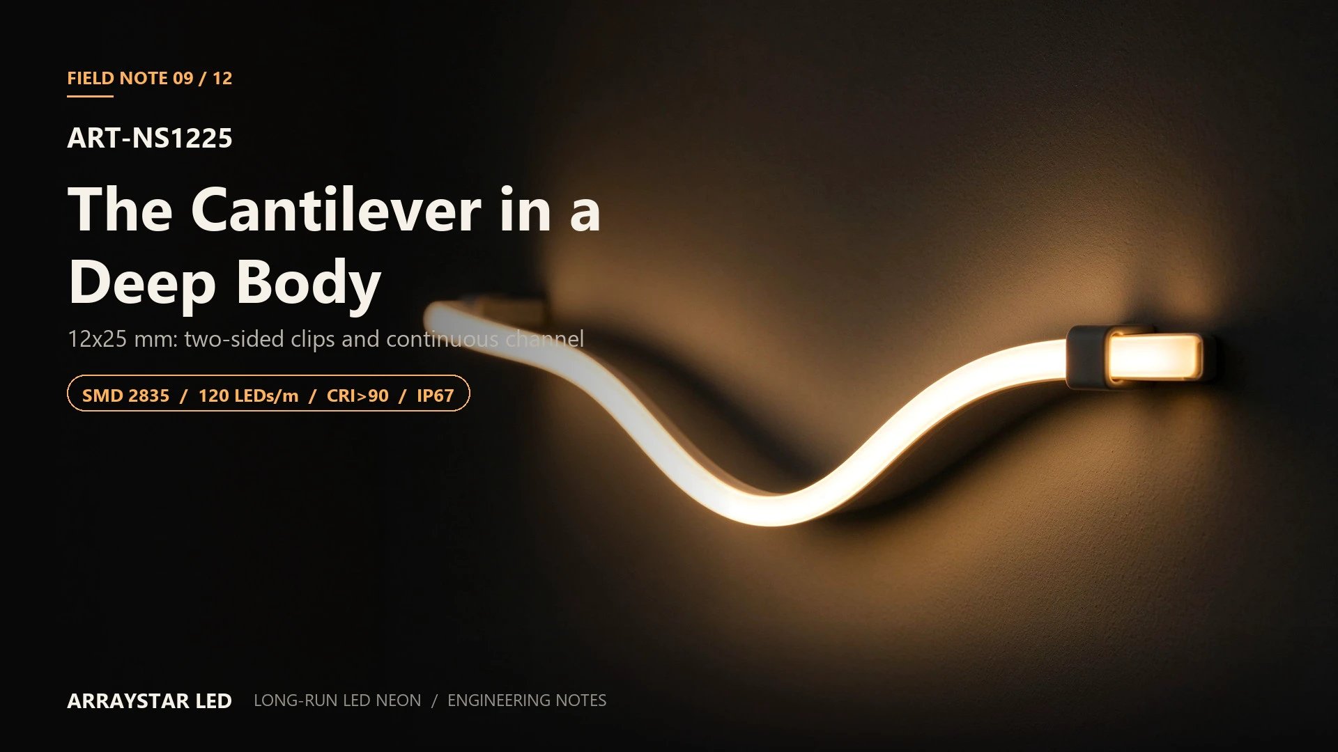
- Clips: 200 mm on straight runs, 100 mm through a bend, plus a clip at each tangent. Offset by half a pitch so no clip sits over an emitter.
- Corners: pre-form on a template; never pull the body around a corner with a tie.
- Cutting: marked points only, 50 mm intervals.
- Sealing: moulded cap and potted joint at every outdoor end; keep the joint on a vertical face.
7. Commissioning checks
| Check | Method | Pass criterion |
|---|---|---|
| Crease at corners | Visual at grazing angle, 24 h after forming | No white fold on the inner wall |
| Line continuity | View at design distance | No ripple, no bright band at clips |
| Feed drop | Head and tail under load | ≤ 3 % of supply |
| Slot temperature | IR probe after 60 min | ≤ 45 °C surface |
| End seal | Visual + continuity | Potted, off the water plane |
8. Engineering FAQ
Can this body make a true 90° corner without a fitting?
Only if the corner radius is at or above the published minimum and the bend is formed on a template. A sharp 90° with no radius will crease the inner wall. Where the detail requires a hard corner, use a corner connector or a pre-formed bend, not a hand bend.
Is 36 V worth it on a 10 m run?
Yes, if the driver is remote or the run would otherwise need more than two taps. At 36 V the current is one third lower, so the feed drop falls by the same proportion. Confirm the 36 V model and driver before committing.
Does the square face show more dirt than a round body?
It shows dirt on the flat face more evenly, and it cleans more easily. The trade is that a scratch on a flat face is visible at grazing angles, where a curved diffuser would hide it.
9. Specification summary
| Parameter | Value |
|---|---|
| Model | ART-NS1010 |
| Cross-section | 10 × 10 mm |
| LED | SMD 2835, 120 LEDs/m |
| Input | 24 V DC (36 V build on request) |
| Power | 10 W/m |
| CRI | >90 |
| Colour | 1800 / 2700 / 3000 / 4000 / 6000 K |
| Cut unit | 50 mm (6 LEDs) |
| Warranty | 3 years |
Detailing a square-section run? Send the corner radii and the channel profile. We will return a bend template and a clip schedule for this body.