Data Signal Glitches Over a Long SPI Run: 330 Ohm Resistor and Level Shifter
- 2026-11-02 15:55
- /
- Arraystar LED
Random pixel glitches over a five-metre data line are almost never a power problem. They are a data-line problem: a 3.3 V logic signal from an ESP32 trying to swing 12 V down a ribbon alongside 5 A of switch-mode noise. I add the 330 ohm series resistor and a level shifter, and the glitches stop.
What the glitches actually look like
A typical complaint: the strip works on the bench at half a metre, but on the ceiling at six metres you get random stray pixels, a snowstorm of colour on the left half, or the first ten pixels flashing a pattern that was never sent. Sometimes it happens only at brightness above 80 percent, sometimes only when a motor on the same circuit starts. The controller firmware looks fine, the power supply reads steady, and the user starts re-flashing the ESP32 to fix it.
What they are seeing is data-line integrity, not power. The SPI-like data wire from the controller to the first pixel is a single-ended 3.3 V or 5 V square wave running at 800 kHz. Over more than about 3 m, and especially when routed next to the 12 V power wires, that square wave degrades: edges round off, noise couples in, and the pixel ICs lose sync.
Why the 330 ohm resistor is step one
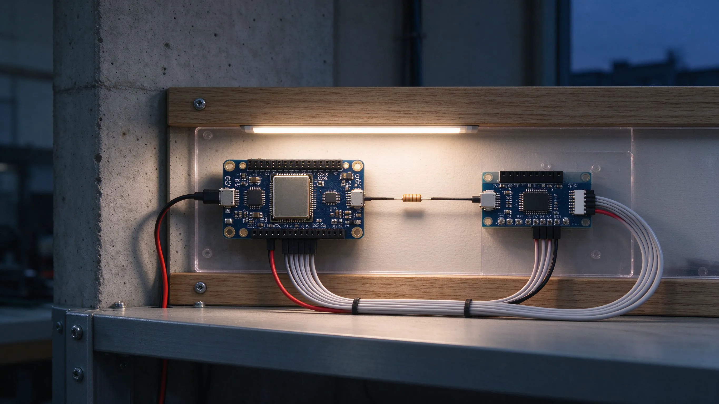
The data trace has a small stray capacitance, typically 50 to 100 pF per metre, and the wire inductance rings like an LC circuit when the edge switches fast. A 330 ohm series resistor right at the controller output, within 10 cm of the ESP32 pin, damps that ring. It also stops the sharp leading edge from ringing back into the pin and causing false clock counts on the pixel IC. This is the single cheapest fix and it takes thirty seconds to solder.
The resistor is free insurance even on short runs; the shifter is the real fix past 3 m.
| Run length of data wire | Symptom without fix | Standard fix |
|---|---|---|
| Under 1 m | Rarely any glitch | Direct wire, no resistor needed |
| 1 to 3 m | Occasional stray pixel at high brightness | 330 ohm series resistor |
| 3 to 8 m | Regular snowstorm, lost frames | Resistor plus level shifter |
| Over 8 m | Noisy, unreliable at any brightness | Shifter plus differential or repeater |
The 3.3 V to 5 V mismatch
Why the ESP32 output is marginal
- ESP32 GPIO pins swing 0 to 3.3 V, not 0 to 5 V.
- WS2811 and SK6812 data inputs want a Vih of 0.7 times Vdd, which is 3.5 V at 5 V supply.
- A 3.3 V high is 0.2 V short of the threshold, and a long wire drops another 0.3 to 0.5 V.
- The pixel sees a weak high, decides it is a zero, and shows a stray pixel.
- A 74HCT245 or a dedicated level shifter brings the signal to a clean 5 V.
On a bench with a 10 cm wire you get away with the mismatch because the signal has not degraded yet. On a six-metre ceiling run, the same 3.3 V edge arrives looking like 2.8 V and the pixel ICs shrug. A bidirectional level shifter module, or a 74HCT245 buffer, between the controller and the strip costs a few dollars and cures the marginal-high problem completely.
Routing and grounding the data wire
Even with a resistor and a shifter, you still pick up noise if the data wire runs parallel to the 12 V feed for six metres. Keep data and power separated by at least 50 mm along the run, and if they must cross, cross at 90 degrees. Use a twisted pair for the data wire and ground, about 10 twists per metre, so the noise couples in common mode and gets rejected by the pixel input.
Ground is the other half of the contract. The ESP32 ground and the strip ground must be connected together, otherwise the 3.3 V logic reference floats. I solder a separate ground wire from the controller ground straight to the strip ground pad, not just through the power supply screw, to keep the reference clean.
When to add a signal repeater
Past about 8 m of data wire, even a clean 5 V square wave degrades enough that the pixel ICs at the far end lose sync. That is the point where I split the run: feed data into the first segment, then tap the DO output of the last pixel in that segment and feed a fresh data line into the next segment. Each pixel re-times the signal, so the run can extend as far as you want, as long as each segment data wire stays under about 5 m.
- Put the 330 ohm resistor within 10 cm of the controller data pin.
- Use a level shifter when the controller is 3.3 V and the strip is 5 V logic.
- Route data at least 50 mm away from the 12 V feed; cross at 90 degrees.
- Split long runs at the DO of a pixel and re-transmit to the next segment.
- Tie controller ground to strip ground with a dedicated wire, not through the PSU.
Recommended Products
Frequently Asked Questions
Why does my LED strip glitch more at high brightness?
Because the power rail sags when all pixels go white, and that sag couples into the data line. The pixel IC sees a lower Vdd, which moves its input threshold down and makes the weak 3.3 V high look even worse. Add a 1000 microfarad bulk capacitor across the strip input, and a 330 ohm series resistor on the data line, before you chase anything else.
What resistor value do I put on the data line?
330 ohm, soldered in series on the data wire within 10 cm of the controller output. Some guides use 470 ohm or even 1000 ohm, but 330 is the sweet spot: it damps the ringing from wire inductance without slowing the edge enough to lose the pixel threshold. On runs under 1 m you can skip it, but I keep it on every build.
Do I need a level shifter between ESP32 and WS2812B?
Almost always, on any run longer than about 1 m. The ESP32 GPIO swings 3.3 V, and a WS2812B at 5 V supply wants a logic high above 3.5 V. On a short bench wire it works by luck. On a ceiling run of several metres, the degraded 3.3 V edge drops below threshold and you get stray pixels. A 74HCT245 or a cheap bidirectional shifter fixes it cleanly.
How long can a single data line run before I need a repeater?
Treat 5 m as the practical limit for one data feed, especially with a 3.3 V source. Past that, tap the DO output of the last pixel in the first segment and feed a fresh data line into the next segment. Every pixel re-times the signal, so you can chain as many segments as you like. Keep each segment data wire under 5 m.
Should data wire run next to the 12 V power wire?
No. Keep them at least 50 mm apart along the run, and cross at 90 degrees if they must meet. The 12 V feed carries switch-mode noise from the driver, and a parallel data wire picks that up as common-mode voltage. Use a twisted pair for data and ground, about 10 twists per metre, and tie the controller ground to the strip ground with a dedicated wire.
Need help with your LED project?
Get factory-direct pricing, free samples and engineering support within 24 hours.
Email: info@arraystarled.com | Phone: +86-0755-2103-6746 | WhatsApp: 0086 1581 8514 077
Need to size your power supply? Use our LED Strip Power Calculator to find the right driver in seconds.