Wiring Long LED Strip Runs: Parallel Feeds, Center Injection and Where Repeaters Belong
- 2026-10-08 17:37
- /
- Arraystar LED
If a long run is bright at the start and dim, pink or flickering at the far end, the strip is not defective - your wiring topology is. Constant-voltage strip loses voltage along every metre of copper, and the single most common amateur mistake is daisy-chaining power through the tiny PCB traces from one end. The fix is an architecture decision, not a brighter strip: feed long runs from the centre or both ends, split big layouts into parallel branches each within their voltage-drop budget, use a power repeater to clone the control signal while injecting fresh power, and step up to 48V when the distances get serious. Plan the feeds before you stick a single metre of tape down and you will never chase a pink tail again.
Why the Far End Goes Dim and Pink
Every metre of strip draws current, and that current has to travel through the copper on the PCB and your feed cable. Copper has resistance, so voltage sags with distance and current - the familiar voltage-drop relationship Vdrop = I x R. At the far end a 24V strip might receive only 21V, and under-voltage LEDs run dim and, on RGB and tunable tape, shift colour because the red, green and blue chips respond differently. The tail looks pink or warm while the head is correct.
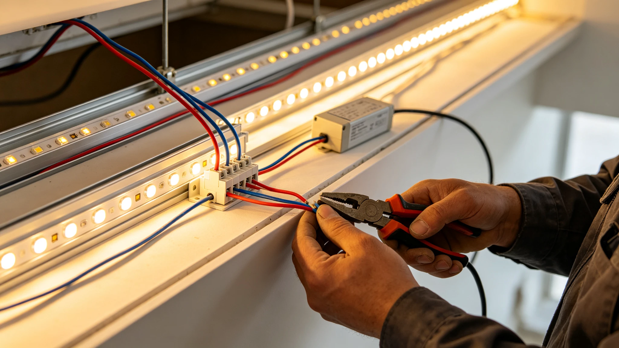
The traces on the strip itself are thin and are not designed to carry the current for twenty metres of tape. When you daisy-chain reel to reel and only feed the first end, every trace upstream is carrying the load of the entire run behind it, which is exactly how you overheat joints and amplify the drop. Power should arrive through real cable at multiple points, not travel the whole length on the PCB.
The Four Wiring Topologies I Actually Use
Choose the topology from the run length and current, not from convenience.
| Topology | How power flows | Best for |
|---|---|---|
| Single-end feed | Driver to one end only | Short runs under ~5m |
| Both-end feed | Driver (or link) feeds both ends | Single long straight run |
| Centre injection | Power fed at the middle, runs split both ways | Long runs, hides the feed centrally |
| Parallel branches | Each run/leg wired directly back to driver | Rooms, cabinets, multi-zone layouts |
| Repeater + injection | Signal cloned, fresh power added mid-run | Very long / high-current animated runs |
| 48V system | Higher voltage, lower current, less drop | Large architectural and commercial runs |
Notice that 'daisy-chain through the strip' is not in the table. You can physically connect reels end to end, but each connected length still needs its own power feed at the spacing the voltage-drop budget allows - the join is mechanical and signal continuity, not a licence to push all the current through one end.
Centre Injection and Both-End Feeds
For one long straight run - a long cove, a bar front, a roof edge - the cheapest high-impact change is to feed from the centre instead of the end. Power injected at the middle splits into two halves, so the worst-case distance current travels is halved, and voltage drop drops to roughly a quarter for the same total length. Feeding both ends gives a similar benefit and is easier when the driver sits at one corner.
On animated, RGB or high-density runs where you want the controller at one end but fresh power further along, I use a constant-voltage power repeater. The repeater takes the control signal (or the PWM output of the master) and re-drives a fresh section using its own local power feed, so the signal continues while the heavy current is injected locally instead of travelling the whole length. The EV2 is the workhorse here - a two-channel constant-voltage repeater I place at every injection point on long single-colour and tunable runs to keep the tail at the same brightness and colour as the head.
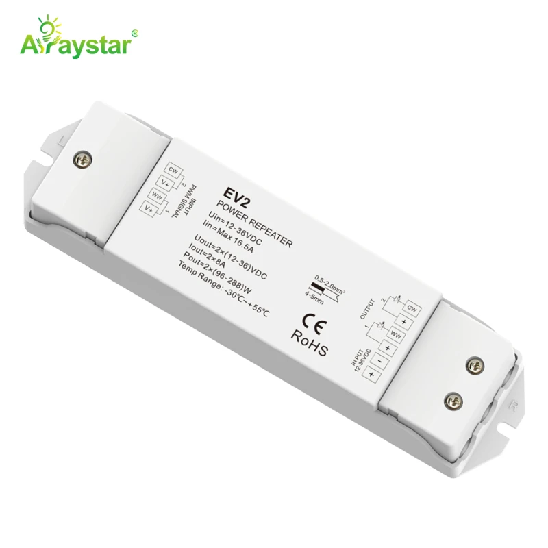
Where to place the repeater
Measure voltage at the tail; when it approaches the lower limit of the strip (roughly 22.5V on 24V tape) that is where an injection point belongs. As a starting rule I plan a fresh feed or repeater every 5-10m on 24V high-density strip and sooner on 12V. Mount the repeater and its local driver somewhere accessible above the ceiling, not buried in the cove.
When I Move Up to 48V
Voltage drop is a current problem, and power in watts equals voltage times current. At 48V the same wattage draws half the current of 24V (and a quarter of 12V), so the voltage drop over a given cable is dramatically smaller and you can run far longer on the same wire gauge. For large architectural coves, long corridors, commercial spaces and outdoor outlines where pulling multiple feed cables is ugly or impossible, 48V strip is the clean answer.
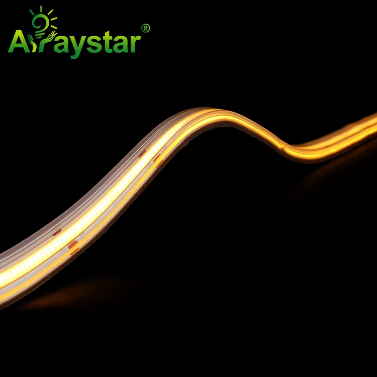
The trade-off is that 48V tape needs a 48V driver and the product range is narrower, and you must still inject power at sensible intervals - 48V reduces the problem, it does not abolish physics. For a long damp or exterior run I reach for 48V IP67 COB: the sealed solid extrusion handles the environment and the voltage lets me cover the length with far fewer visible feeds and drivers.
Parallel Branches and Sizing the Driver
When a layout is several separate runs - a kitchen with cove, under-cabinet and plinth circuits, or an office perimeter with multiple walls - wire each leg in parallel directly back to the driver (or to a distribution block) rather than looping one leg through the next. Each parallel leg sees the full driver voltage, so no leg is starved by the one before it, and a fault on one leg is isolated and easy to find.
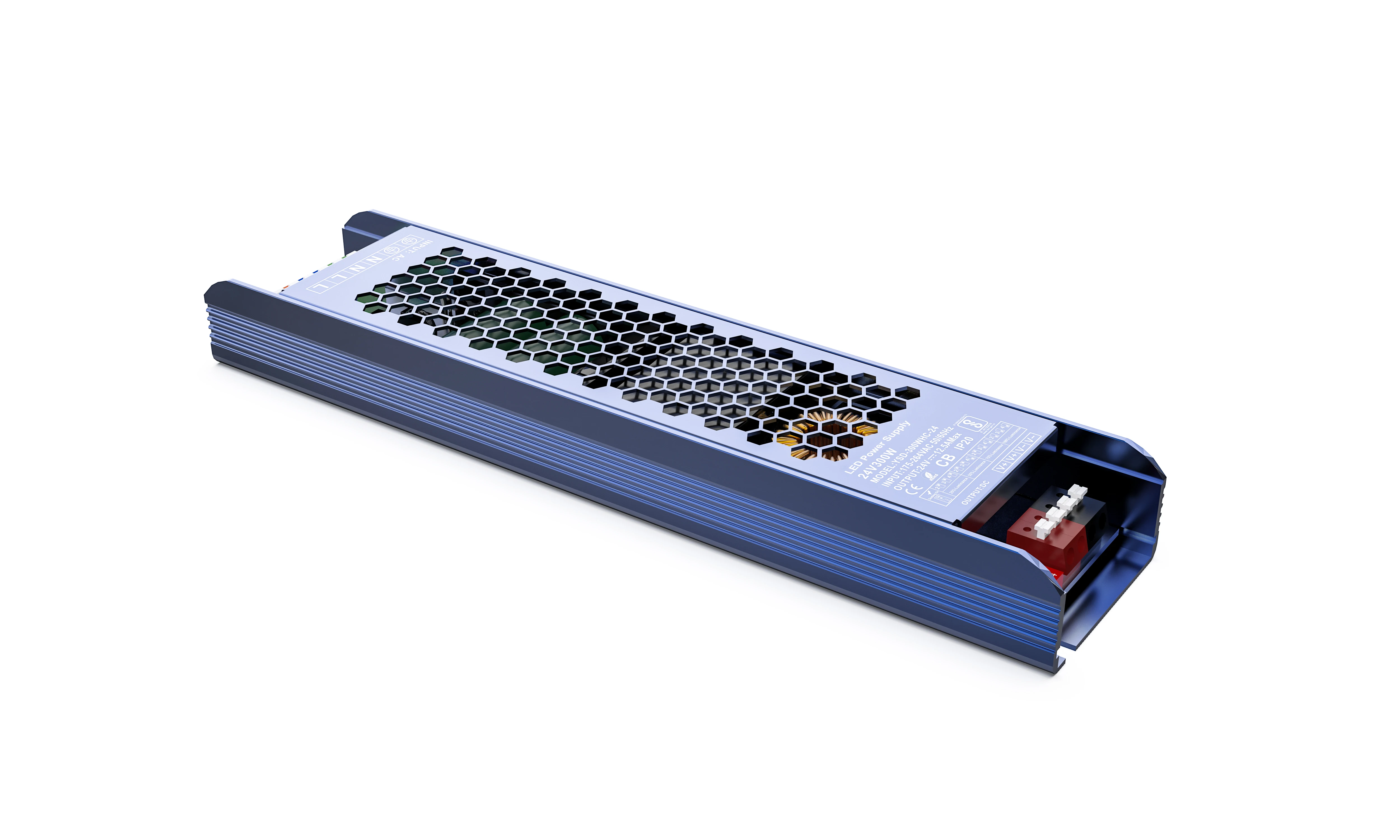
Size the driver for the sum of every parallel branch plus 20% headroom. On a multi-branch dimmable job I use a single dimmable supply large enough for the whole load - a 300W dimmable driver comfortably covers a typical open-plan perimeter - and distribute from a terminal block, with each leg fused. One dimmable source keeps every branch dimming in sync, which separate small drivers never quite do.
When in doubt go one cable size thicker; the copper is cheaper than re-opening a cove.
| Cable (mm2) | Rough 24V capacity over 5m | Use |
|---|---|---|
| 0.5 | Short low-current tails | Single short run pigtails |
| 0.75 | Up to ~6-8A | Standard room branches |
| 1.0 | ~10A | Longer 24V runs |
| 1.5 | ~15A | Long feeds / 12V high-current |
| 2.5 | Main distribution | Commercial parallel manifolds |
The Wiring Rules I Tick Off Every Job
- Calculate total watts per driver and add 20%; never run a supply flat out.
- Plan injection points from a voltage measurement, not by eye - keep tail voltage within spec.
- Prefer centre or both-end feeds for single long runs; use parallel branches for multi-zone layouts.
- Use repeaters to clone the signal while injecting fresh local power on long animated runs.
- Step up to 48V when pulling extra feed cables is impractical; still inject at intervals.
- Fuse each branch, use properly rated cable, and keep all polarity and colour coding consistent.
Get the topology right on paper before installation and the rest is mechanical. Every 'faulty strip dim at the end' call-out I attend turns out to be a single-end feed that should have been centre-injected from day one.
Recommended Products
Frequently Asked Questions
Why is one end of my LED strip brighter than the other?
That is voltage drop. Current travelling through the thin PCB copper and feed cable loses voltage with distance, so the far end receives less voltage and runs dim, and on RGB or tunable strip shifts toward pink or warm. Feed the run from both ends or the centre, shorten the distance between power injection points, use thicker cable, or move to 48V strip. The tape itself is almost never the cause.
How often do I need to inject power into a long LED run?
Measure the voltage at the tail and inject before it falls below the strip's rated minimum (about 22.5V for 24V tape). As a practical starting point, plan a fresh feed or repeater roughly every 5-10m on 24V high-density strip and sooner on 12V, which drops faster because it carries more current. Higher density (more watts per metre) and thinner cable both shorten that spacing; 48V extends it considerably.
What does an LED power repeater actually do?
A constant-voltage repeater takes the control or PWM signal from your master controller and re-drives a fresh section of strip using its own local power supply. This lets the signal continue along an arbitrarily long run while the heavy current is injected locally at each repeater instead of travelling through the whole length of PCB. It is the correct way to extend single-colour, tunable-white and PWM-controlled runs without the far end dimming.
Should I wire LED strips in series or parallel?
Constant-voltage LED strips are wired in parallel across the supply, each run receiving the full 12V/24V/48V. Wire separate legs back to the driver or a distribution block so no leg is starved by the one before it and faults stay isolated. Connecting constant-voltage strips 'in series' so current passes through one run to reach the next causes exactly the voltage-drop and dimming problems you are trying to avoid.
Is 48V LED strip better than 24V for long runs?
For long architectural and commercial runs, yes: at 48V the same wattage draws half the current of 24V, so voltage drop is far smaller and you need fewer injection points and can use thinner cable. It is sealed IP67 COB at 48V that I spec for long damp and exterior runs. For short interior coves 24V remains cheaper with a wider product choice, so only move to 48V when the distance genuinely justifies it, and always use a matching 48V driver.
Need help with your LED project?
Get factory-direct pricing, free samples and engineering support within 24 hours.
Email: info@arraystarled.com | Phone: +86-0755-2103-6746 | WhatsApp: 0086 1581 8514 077
Need to size your power supply? Use our LED Strip Power Calculator to find the right driver in seconds.