Neon Flex on Vibration-Prone Signs: Strain Relief and Secure Fixing
- 2026-10-28 10:03
- /
- Arraystar LED
A vibrating sign face shears neon flex at the solder joint, because the flex moves and the driver tail does not. After a few failed storefront signs, I now loop the incoming cable, space clips tighter on the feed end, and choose a flexible silicone or TPU jacket that flexes instead of cracking.
Where vibration actually breaks neon flex
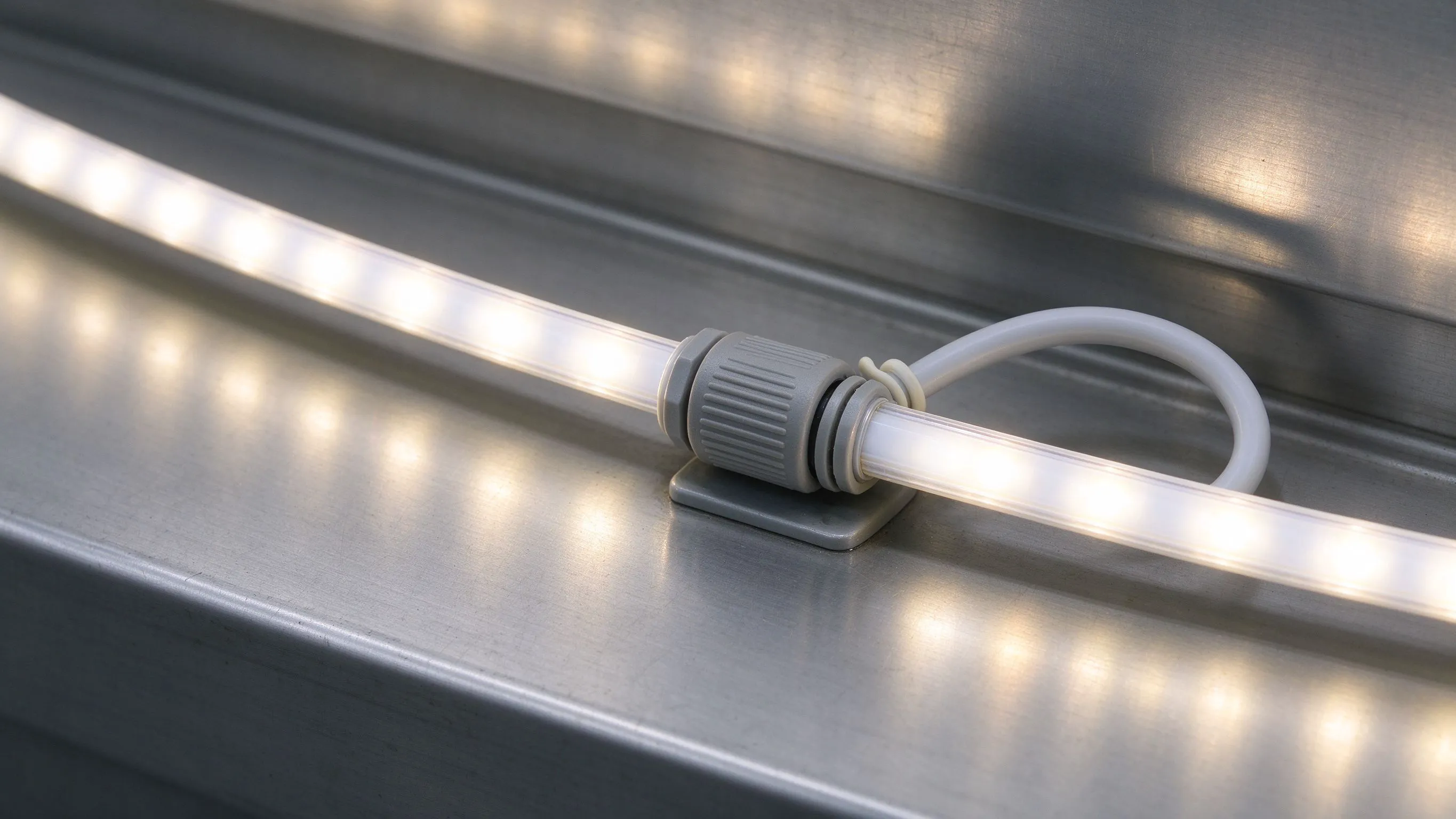
Vibration does not tear neon flex out of its clips; it fatigues the joint at the point where the stiff, unsupported wire tail meets the moving flex. On a spinning sign face, a vent fan on the roof, or a door that slams beside the channel, the solder leg rocks back and forth until a hairline crack forms in the solder fillet. That crack starts as a flicker on one segment, then grows to a dead half-metre. I have pulled failed runs apart and the flex itself is nearly always intact — the break is always at the transition. I once traced a flicker to a fan on the roof three floors up; the flex was fine, the solder leg was cracked clean through where the tail entered the jacket.
Strain relief: the loop and the first clip
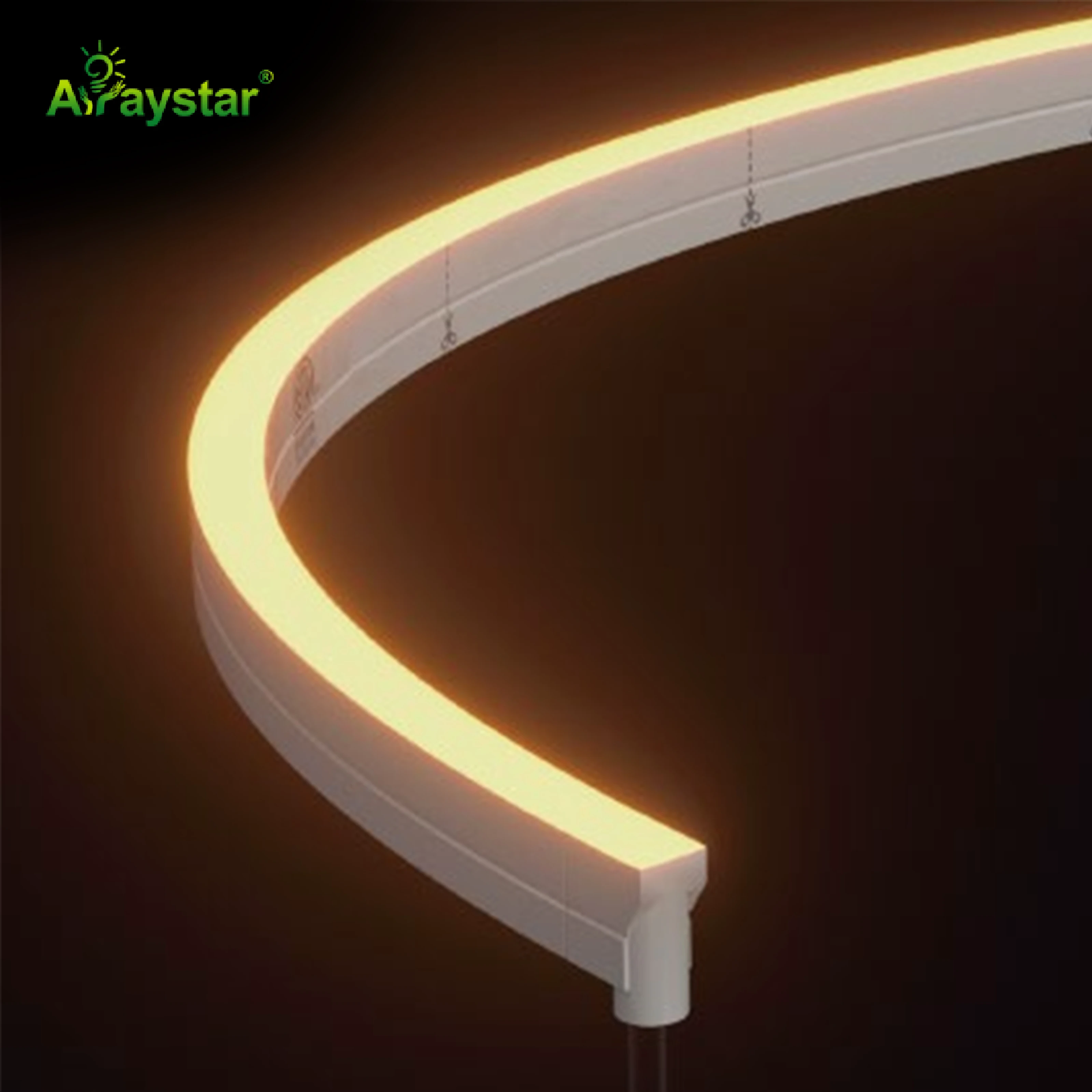
- Leave a 30–50 mm service loop in the flex right where the feed cable enters, so movement dies in the loop instead of at the solder.
- Space clips at 50–75 mm near the feed end, wider (100–150 mm) in the middle of a straight run.
- Do not over-tighten the first clip; a clamped jacket fights the flex and turns the clip edge into a fatigue point.
- Anchor the incoming 24V cable separately to the sign frame so the cable is not pulling on the joint.
The single best fix I know is the service loop. A gentle U-bend of 30–50 mm in the flex absorbs the micro-movement before it reaches the solder. I see so many installs where the flex is pulled drum-tight from the driver to the first clip; that is exactly the setup that cracks in a month. On a 2 m sign panel I would put clips at 60 mm near the feed, then widen to 120 mm along the straight middle, and leave the loop where the cable enters so the shake never reaches the fillet.
Choosing a jacket that survives the shake
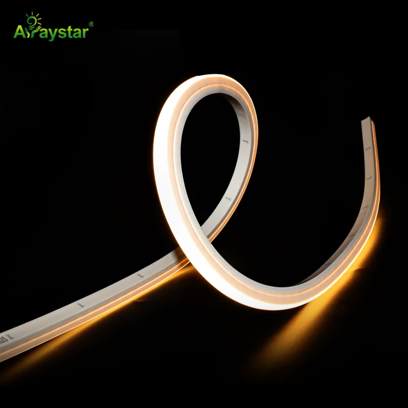
TPU and silicone take the shake; PVC resists it and eventually breaks.
| Jacket | Flexibility | Vibration fit | Typical sealing |
|---|---|---|---|
| Silicone extrusion | Very flexible | Excellent; flexes, does not crack | IP65–IP68 |
| TPU extrusion | Flexible, tough | Excellent on moving parts | IP68 |
| PVC smooth | Stiffer | Prone to cracking at joints | IP65–IP67 |
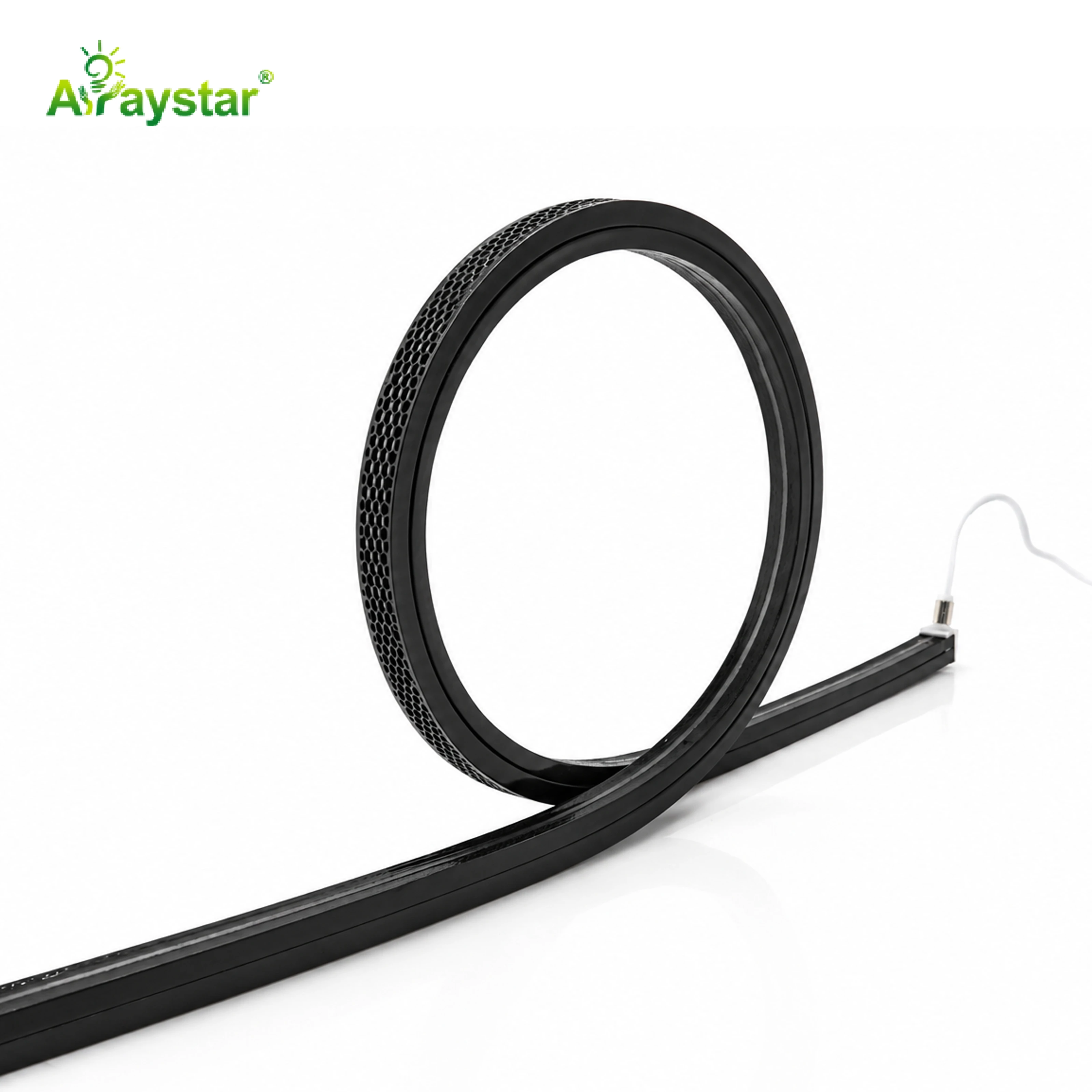
On a genuinely vibrating sign face I reach for a TPU or full silicone extrusion rather than a stiff PVC jacket. The rigid black 12×12 mm anti-glare profiles look great on a fixed wall, but on a panel that wobbles in traffic I want something that gives with the motion. The anti-glare TPU strips in this range are built for outdoor IP68 duty and tolerate the repeated bend. The test I run on the bench is a hand bend: if the jacket fights me and whitens, I keep that profile for a static wall and swap to the flexible build for the panel that moves.
Electrical details that matter under shake
Vibration amplifies a weak solder joint, so I solder and shrink-shrink every feed rather than relying on push-in connectors. I use 18–20 AWG for the 24V feed and keep the driver mounted on a fixed, braced part of the structure — never on the vibrating panel itself. If the sign is outdoors as well as vibrating, I coat the joint with self-amalgamating tape rather than plain heatshrink, because water and micro-movement together kill a joint fastest. I wrap the tape from the joint outwards, stretching it by half its width, so it seals under tension instead of loose. Voltage drop on a short sign run is rarely the issue; a 23–25V window at the flex end is plenty.
Field checks before sign-off
Before I hand a vibrating sign over, I run it for an hour while I stand next to it and watch for any faint flicker at the feed joint. I also press the service loop and feel whether the clips are biting or just holding. If a clip is crushed into the jacket, I swap it for a wider one. The anti-glare black 12×12 mm profile works beautifully on a static wall feature, and I keep it for those; the moment the panel moves, I move up to the flexible TPU build and leave the loop. My sign-off checklist is short: loop left at the feed, clips spaced tight at the tail, driver off the panel, joint taped outwards, and an hour of flicker watch before I walk away.
Recommended Products
Frequently Asked Questions
How tight should neon flex clips be on a vibrating sign?
Snug, not crushed. A clip that bites into the jacket creates a hard fatigue point; I space them 50–75 mm near the feed and 100–150 mm along the straight run.
What is a service loop and why does it help?
It is a 30–50 mm gentle U-bend in the flex just after the feed. The loop absorbs micro-movement so the solder joint at the driver tail does not rock back and forth until it cracks.
Should I mount the driver on the vibrating sign panel?
No. Mount the driver on a fixed, braced part of the structure. A driver that shakes with the panel shortens its own life and transmits movement straight into the feed joint.
Which jacket is best on a moving sign face?
TPU or full silicone extrusion. They flex with the motion instead of fighting it; a stiff PVC jacket looks fine on day one and cracks at the joints within a season.
Do push-in connectors work on vibrating signs?
I avoid them. I solder every feed joint and use dual-wall heatshrink, or self-amalgamating tape outdoors, because push-in contacts loosen under repeated micro-movement.
Need help with your LED project?
Get factory-direct pricing, free samples and engineering support within 24 hours.
Email: info@arraystarled.com | Phone: +86-0755-2103-6746 | WhatsApp: 0086 1581 8514 077
Need to size your power supply? Use our LED Strip Power Calculator to find the right driver in seconds.