Mitring Aluminum Profile Corners: End-to-End Light Without a Dark Joint
- 2026-10-28 10:04
- /
- Arraystar LED
A dark V at the corner of an LED run is the first thing a client notices. It comes from a mitre cut that leaves the strip end exposed or a gap between the two channel halves. I have cut enough of these to know the joint is won before the saw starts.
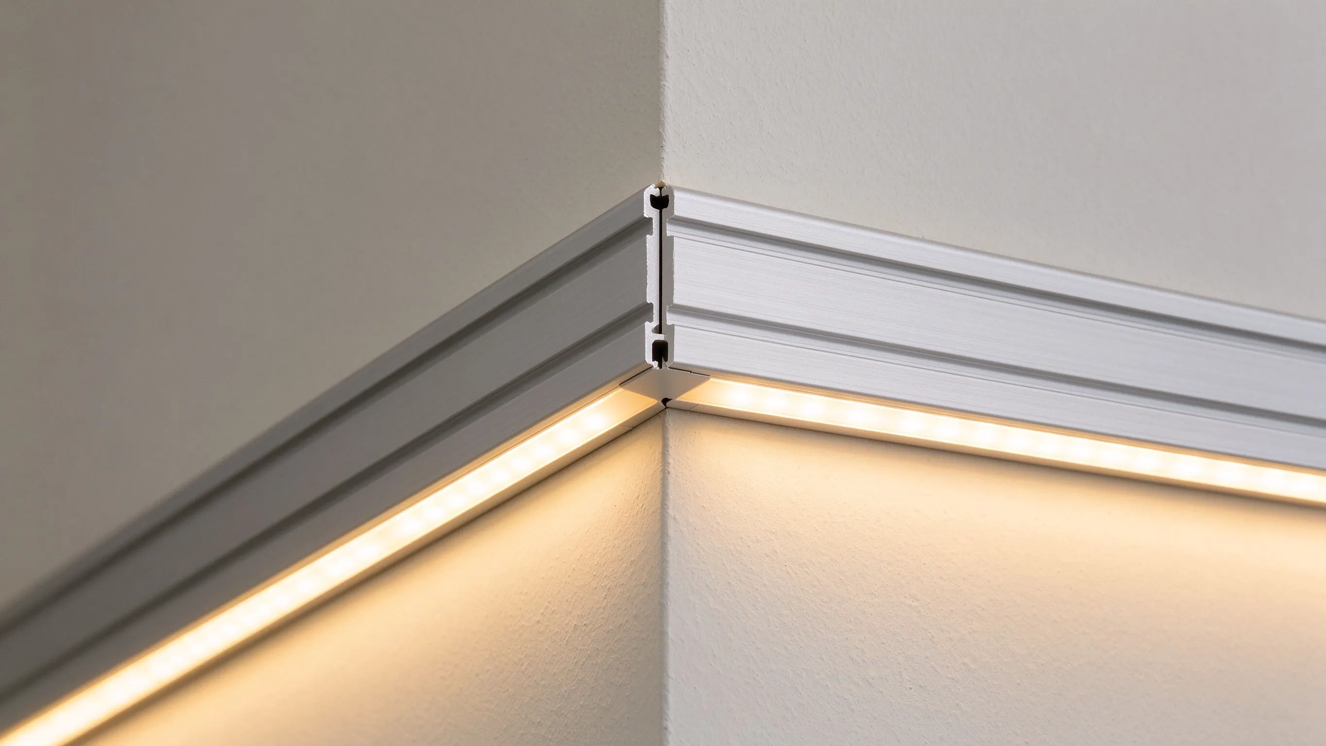
Why corners go dark
When you cut two straight channels at forty-five degrees to form a right-angle, the LED strip inside has to turn that same corner. The strip itself cannot bend on the soldered side tight enough to fill the inside of the V, and if you cut the channel mitre too deep, the diffuser ends and leaves a gap where no light escapes. The result is a black triangle at the exact point the eye is drawn to.
On a staircase handrail job I watched a fitter cut both channels at forty-five, butt them together, and leave the strip going straight into the wall. The corner was a dead black notch. We ended up re-routing with a short flexible tail and a corner piece, but the lesson stuck: plan the strip path before you cut the aluminium.
The three corner failure modes
- Strip cannot bend tight enough, leaving an unlit inner radius.
- Mitre gap between the two channel halves shows as a dark V.
- Diffusers cut at the mitre leave a mismatch at the joint.
Cutting the mitre so the light survives
I cut the channel ends at forty-five on a mitre saw with a fine-tooth aluminium blade, taking the cut slowly to avoid burrs that stop the two halves seating. The strip is the constraint: a standard 8 mm SMD strip needs roughly a 30 to 50 mm minimum bend radius. If the corner inner radius is tighter than that, the strip will kink and one LED dies every time.
Choose the joint method by strip radius, not by how it looks on paper.
| Corner type | Method I use | Min strip radius |
|---|---|---|
| 90-degree inside corner | Mitre two straight channels | 30-50 mm |
| 90-degree outside corner | Dedicated corner profile | No bend needed |
| Tight radius (<30 mm) | Segmented short pieces | N/A |
| Large sweep | Flexible / bendable channel | Per datasheet |
Seating the diffuser across the joint
The diffuser is where the amateur job shows. I cut each diffuser at the same forty-five angle but leave it a fraction long, then trim with a sharp knife so the two halves meet flush at the apex. A small bead of clear neutral silicone at the joint stops dust and insects getting inside, and keeps the diffuser from lifting as the channel warms.

Powering through the corner
I always feed the strip so the corner is not the point where voltage droop piles up. On a long perimeter run, inject power at the midpoint of each leg rather than at the corner itself, otherwise the turn is where you first see the corner dim to warm white. A corner piece with a tiny flex tail lets the strip bend around without kinking the PCB.

The corner check on first switch-on
Before I leave any job, I run my finger around every corner in the dark. A good joint feels flush and looks like one continuous line; a bad one shows a dark triangle, a silver step, or a warm tinge where voltage droop sits. I touch up the silicone and re-seat the diffuser on the spot rather than waiting for the client to phone.
The tools make a difference here. I cut mitres on a mitre saw with a 120-tooth aluminium blade, never a hacksaw, because a rough edge stops the two halves seating flush and leaves that tell-tale silver line. After cutting I deburr both faces with a fine file, blow out the swarf before inserting the strip, and dry-fit the corner with the diffuser in place before any fixing goes in. A dry fit takes five minutes and catches the mismatch on the bench, not on the wall at night.
Recommended Products
Frequently Asked Questions
How do I stop a dark gap at the LED channel corner?
Cut both channel halves at forty-five with a fine aluminium blade and seat them flush, and route the strip through a short flexible tail so it bends around without kinking. A 30-50 mm inner radius is the floor; tighter than that and you lose the corner LEDs.
Can I bend LED strip around a sharp ninety-degree corner?
A standard 8 mm strip needs a 30 to 50 mm minimum bend radius on its soldered side. A sharp ninety without radius kinks the PCB and kills LEDs. Either use a corner profile that routes the strip through a flex section, or build the turn from short segmented pieces.
Why is my LED corner dimmer than the rest?
Likely voltage droop accumulating right at the corner, especially on long runs fed from one end. Inject power at the midpoint of each leg rather than at the corner, and keep corner runs under five metres from the feed. The warm tinge is the resistor chain sagging.
Should the diffuser be cut at the mitre angle?
Yes, but leave it a fraction long and trim with a sharp knife so the two halves meet flush at the apex. A tiny bead of clear neutral silicone at the joint stops dust and keeps the diffuser from lifting as the channel heats. Do not use acetic-cure silicone near aluminium.
Mitre cut or corner profile for outside corners?
I use a purpose-made outside corner profile rather than a mitre whenever aesthetics matter. The corner piece carries the diffuser and lip on both faces at the correct geometry, so the light turns cleanly. Mitres are cheaper but the joint mismatch shows up at the first switch-on.
Need help with your LED project?
Get factory-direct pricing, free samples and engineering support within 24 hours.
Email: info@arraystarled.com | Phone: +86-0755-2103-6746 | WhatsApp: 0086 1581 8514 077
Need to size your power supply? Use our LED Strip Power Calculator to find the right driver in seconds.