External Corner Mitres for Neon Flex: Clean Turns Without Bulging
- 2026-10-28 10:02
- /
- Arraystar LED
An external corner on neon flex wants to bulge and kink, and ninety percent of installers fight it by bending harder. I cut a mitre, couple the two ends cleanly and let the geometry do the work. The turn then reads crisp from the road instead of looking like a sore thumb.

Why an external corner bulges
Neon flex is an extruded silicone tube over a flat PCB. When you bend it around an external ninety-degree corner, the inside face compresses and the outside face stretches. Because the silicone is thicker than the PCB, the outside wall cannot pull flat, and it bows outward into a bulge. From the road, that bulge reads as a fuzzy, fat corner; close up, it is a permanent kink in the diffuser that never looks right. Forcing the bend tighter only makes the bulge worse.
On a corner-fascia job I watched a new installer wrestle a 1010 tube around a building corner for forty minutes, tape over tape, heat gun on, until the corner bulged out past the line of the sign. We cut it out, re-cut both ends at forty-five degrees, joined them with a small inline connector, and the corner dropped straight into line. The lesson stuck with me: do not bend around corners, join them.
The two ways to handle an external corner
- Bend around it: flexible but bulged, fine for small sections under 6 mm.
- Cut a mitre and join: crisp, flat, works for sections from 8 mm upward.
- Use a purpose-made corner connector: clean but adds a visible seam.
How to cut the mitre
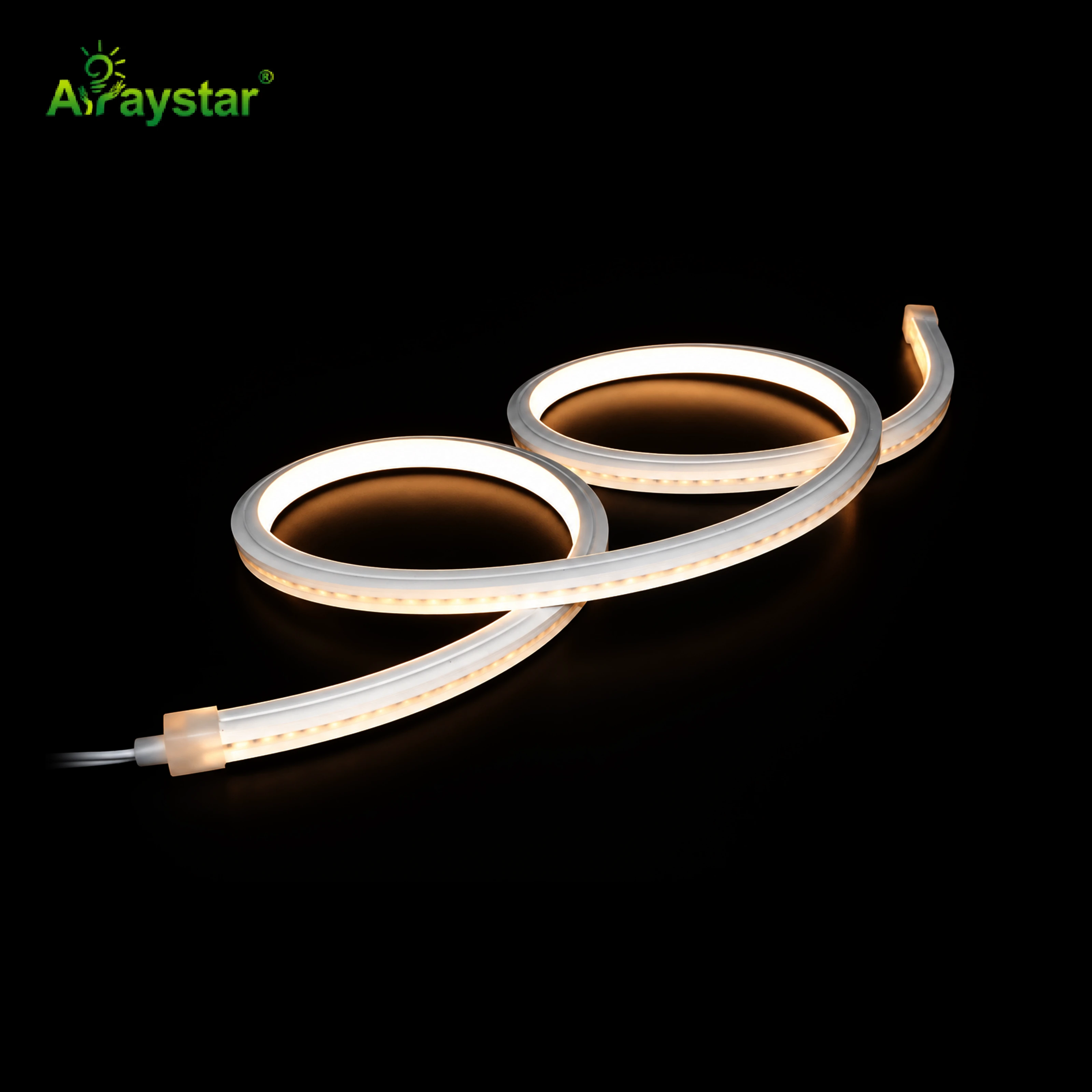
I measure the corner location on the wall, mark the tube on the bench, and cut each end at forty-five degrees using a sharp hobby knife against a steel ruler. The cut must land on a marked copper pad, never between LEDs, and I leave the silicone outer jacket slightly longer than the PCB so the two halves meet cleanly without the solder joint bearing on the corner. The two forty-five-degree faces come together into a clean ninety-degree external point.
Bend small sections; mitre anything 8 mm up, where the silicone wall is too thick to pull flat.
| Tube section | Corner method | Radius / cut |
|---|---|---|
| 4 mm mini flex | Bend around | Min 30 mm internal radius. |
| 6 mm flex | Bend around or mitre | Mitre if bulge shows. |
| 8-10 mm flex | Mitre and couple | 45-degree cut on a copper pad. |
| 12 mm and above | Mitre, never bend | Couple with inline connector. |
The cut face has to be flat. A ragged cut leaves a hairline gap at the corner that lights up as a bright line. I trim the face with a fresh blade until the two halves mate with no daylight between them when held together.

Coupling the two halves at the corner
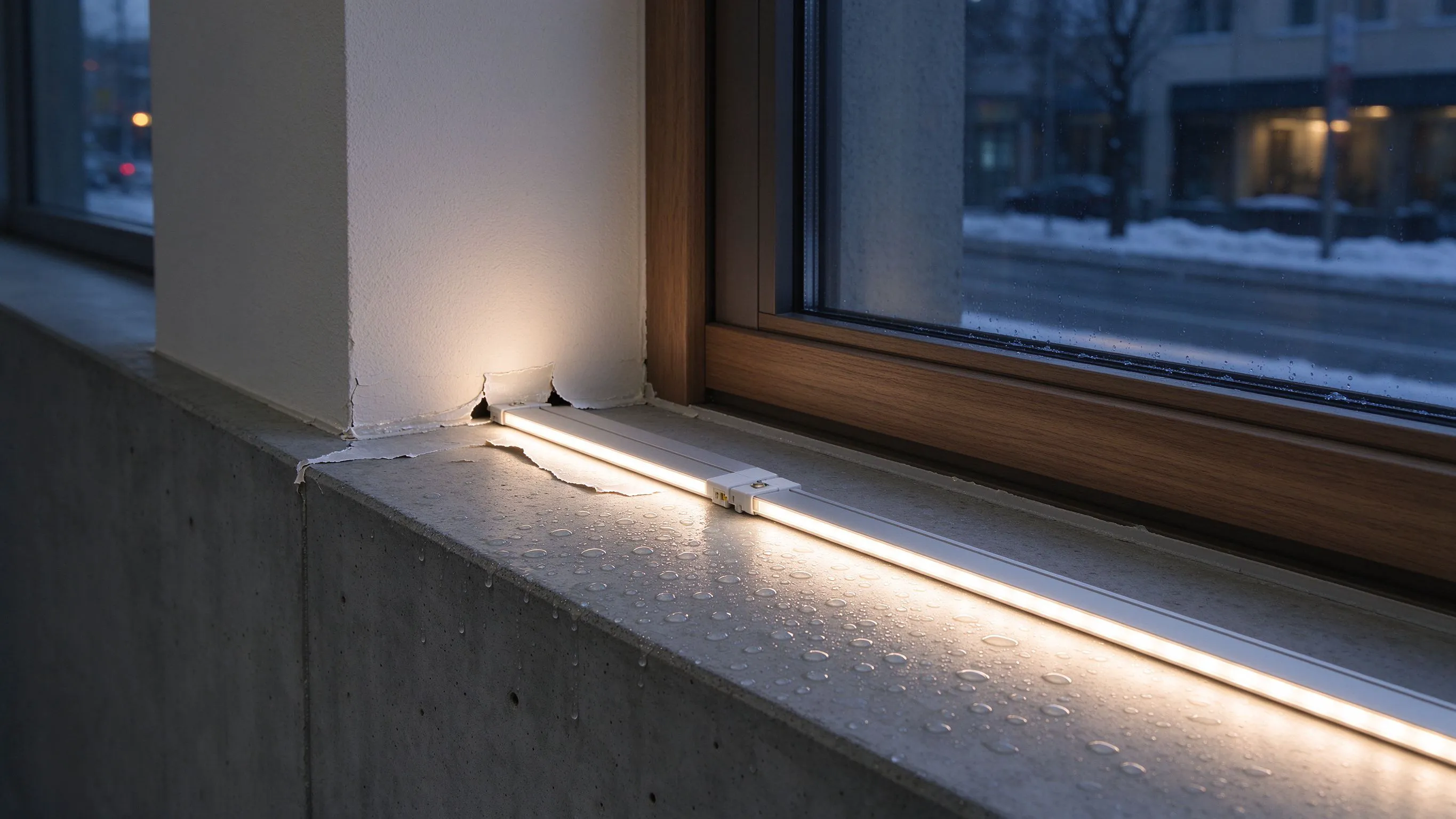
Once the two forty-five-degree ends are ready, I solder the wires inside a small inline silicone connector that sits on the rear face of the corner. The connector is barely visible from the pavement, and it keeps the joint mechanical rather than relying on solder alone. I slide a heat-shrink with adhesive liner over the solder, then bed the connector in neutral-cure silicone so the corner stays weatherproof. The front diffuser faces meet at the point and read as one continuous line.
- Cut both ends on a copper pad, never between LEDs.
- Use a rear-mounted inline connector; keep the front face clean.
- Heat-shrink with adhesive liner over every solder joint.
- Bed the connector in neutral-cure silicone for exterior work.
Supporting the corner so it does not sag
The corner joint is the heaviest point in the run because it carries two directions of tube. I put a clip or a standoff within 30 mm of the corner on both sides, and I leave a small 10 mm service loop inside the joint so thermal movement does not pull the mitre apart. On a long two-storey run, that corner is the first place a crack will appear if it is left unsupported.

The on-site check before leaving
I power the sign up and walk back to the opposite side of the road. A crisp corner reads as a single sharp point; a bad mitre shows as a bright line, a bulge or a dark gap. If I see any of those, I climb back up and re-cut. By the time the client walks out of the building, the corner has to look as if the tube grew around the building, not as if someone taped two pieces together.
- View the corner from road distance, not from the ladder.
- Check the diffuser faces meet with no bright gap.
- Feel the connector; it should run no warmer than the rest of the tube.
- Photograph the finished corner for the maintenance file.
Recommended Products
Frequently Asked Questions
Can I just bend neon flex around an external corner?
On small sections up to 6 mm, yes, if you respect the minimum bend radius. On 8 mm and above, the silicone wall is too thick and the outside face bulges permanently. That bulge reads as a fuzzy, fat corner from the road. For sections 8 mm and up, cut a forty-five-degree mitre on each end and couple them.
How do I cut a clean mitre in neon flex?
Mark the tube on the bench, align a steel ruler, and cut each end at forty-five degrees with a fresh sharp blade. Always cut on a marked copper pad, never between LEDs. Trim the cut face until the two halves mate with no daylight between them. A ragged cut leaves a hairline gap that lights up as a bright line at the corner.
What connector should I use at a mitred corner?
A small inline silicone connector mounted on the rear face of the corner, so the front diffuser line stays clean. Solder the wires inside, slide adhesive-lined heat-shrink over the joint, and bed the connector in neutral-cure silicone for exterior work. The connector is almost invisible from the pavement and keeps the joint mechanical.
Why does my neon flex corner have a bright line?
Almost always a hairline gap between the two mitred faces, lit from inside. The cut was not flat or the two halves were not pushed fully together. Re-trim the cut faces until they mate with no daylight, re-join them, and the bright line disappears. If the gap is on the solder joint itself, add a touch of neutral silicone inside to block the light leak.
Do I need extra support at a mitred corner?
Yes. The corner joint carries two directions of tube, so put a clip or standoff within 30 mm on both sides, and leave a 10 mm service loop inside the joint. That loop lets the tube move with thermal expansion so the mitre does not pull apart by February. An unsupported corner is the first place a crack appears.
Need help with your LED project?
Get factory-direct pricing, free samples and engineering support within 24 hours.
Email: info@arraystarled.com | Phone: +86-0755-2103-6746 | WhatsApp: 0086 1581 8514 077
Need to size your power supply? Use our LED Strip Power Calculator to find the right driver in seconds.