Dark Spots at the Ends of Joined Rigid LED Bars
- 2026-11-02 15:55
- /
- Arraystar LED
Two rigid LED bars butted end to end almost always leave a dim pad at the join. It is not a bin issue and it is not a bad bar; it is the bus-bar running out of copper right where the second bar starts drawing current.
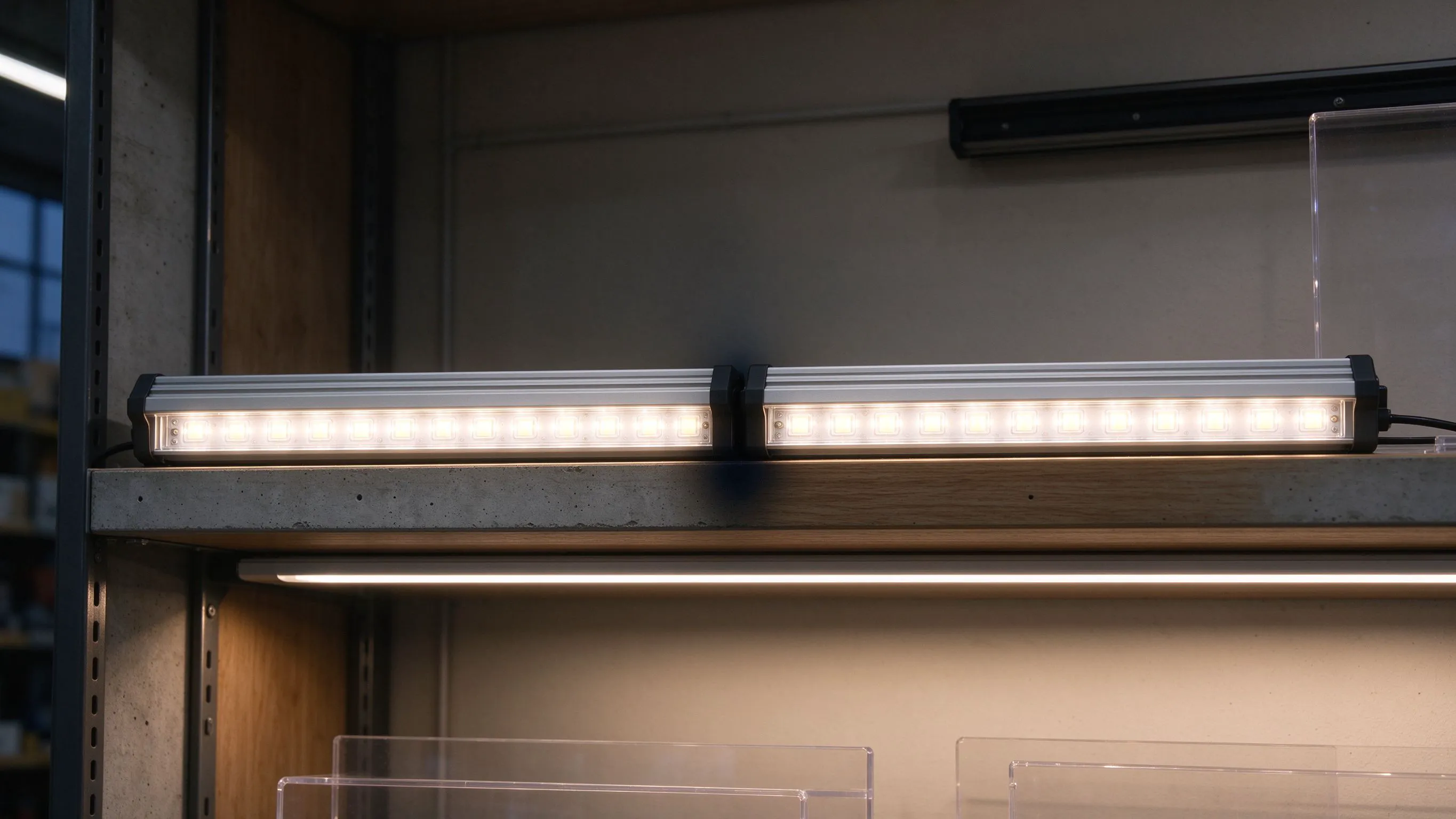
The dark spot that shows up only on a long shelf run
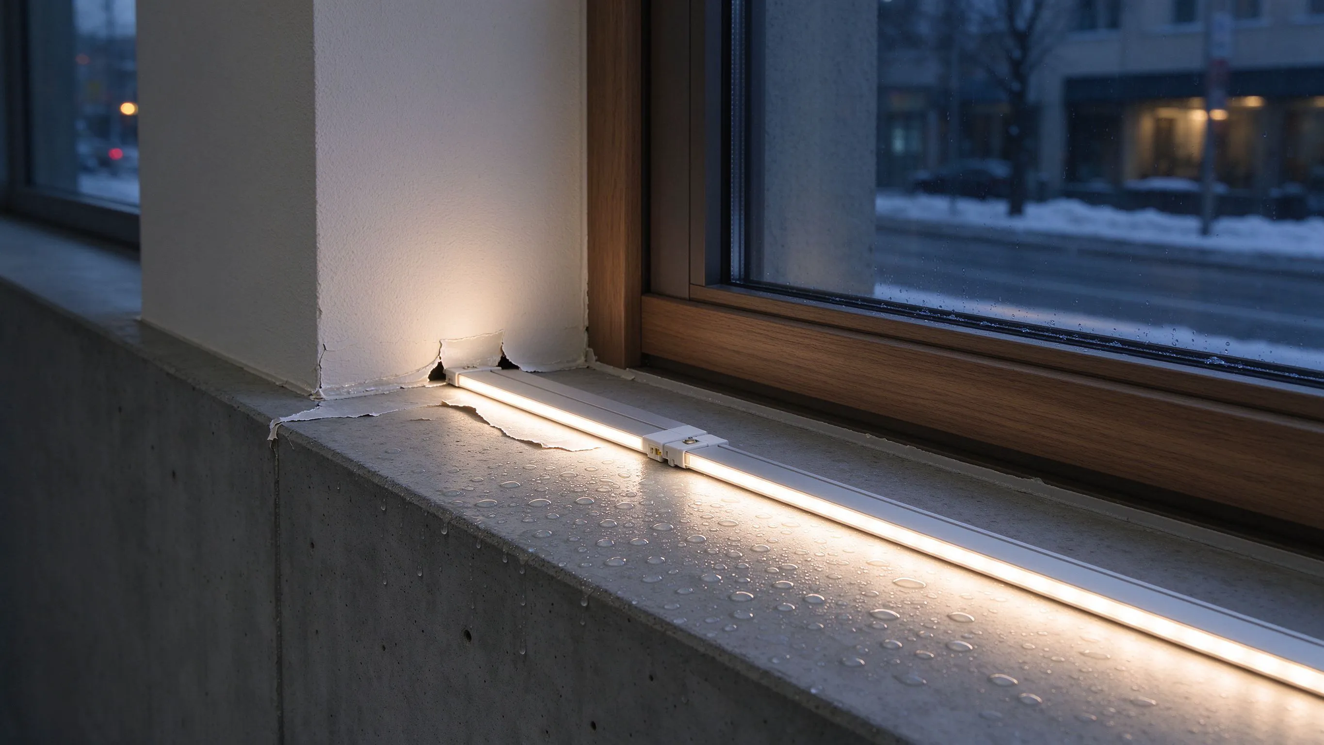
A client runs six 480 mm rigid bars end to end under a shelf, and the join between bar three and four has a visible dim band right at the end pads. The rest of the run looks even. He sends the bars back under warranty; they test fine on the bench. The problem is the join itself, not the bar.
Rigid bars carry current along copper traces on the PCB, not along a separate bus wire. Every LED pulls a little current along the trace, and voltage drops a fraction of a volt by the time you reach the far end. When you butt two bars together on a 5.5 mm connector pad, the contact resistance at that pad adds another drop, and the LEDs right next to it read dimmer. On a short 500 mm run you never see it; on a 3 m shelf you do.
- The dim band is always at the join, not in the middle of a bar.
- It gets worse as you add more bars in series.
- It is usually symmetrical, a little dim on both sides of the pad.
Why the end pad on a rigid bar is the weak point
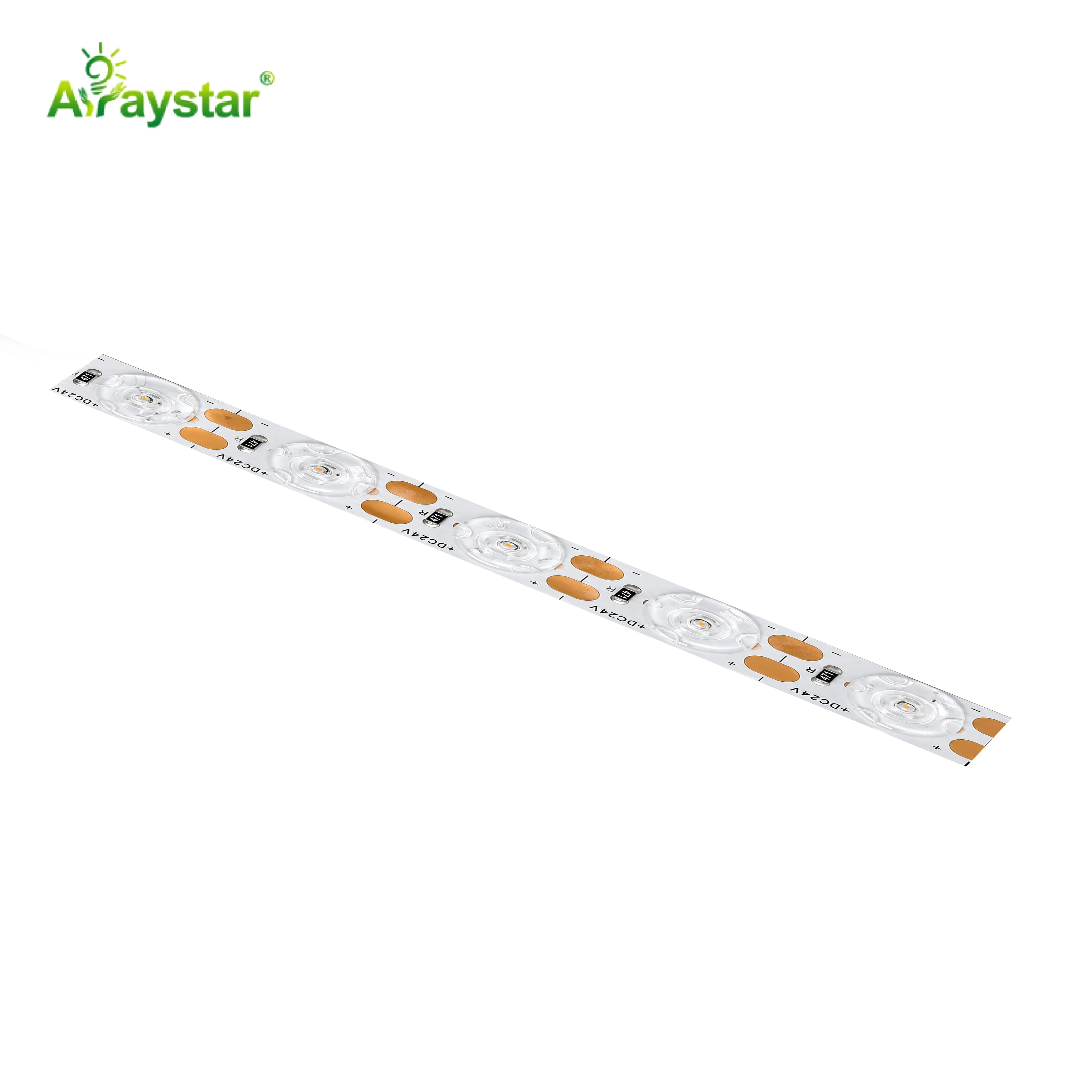
A rigid bar PCB uses 1 to 2 ounce copper. The copper area is sized for the LED count per bar, and the end pads are deliberately narrow because they only carry the bar own current. When you chain a second bar off that pad, you are asking a pad sized for one bar to feed two, and the voltage drop at the contact jumps. The first few LEDs on the second bar run 0.3 to 0.5 V low, which on a 24 V strip can read 10 to 15 percent dimmer.
I measure this on the bench before I blame the bins. A multimeter across the last LED pad on bar one and the first pad on bar two tells me exactly what is happening. If there is a 0.4 V difference at full load, no amount of bin selection fixes it; the contact and the bus area have to be addressed.
How to join bars so the end pad does not dim
Bridging the pad with copper removes most of the visible step.
| Join method | Typical contact drop | Visible dark band? |
|---|---|---|
| 5.5 mm snap pad, no bridge | 0.3-0.6 V | Yes, common |
| Solder bridge across both pads | 0.1-0.2 V | Mostly gone |
| Separate 24V feed at each join | <0.05 V | None |
| Wide copper joint connector | 0.05-0.1 V | Very faint |
Spreading the feed: where to inject power
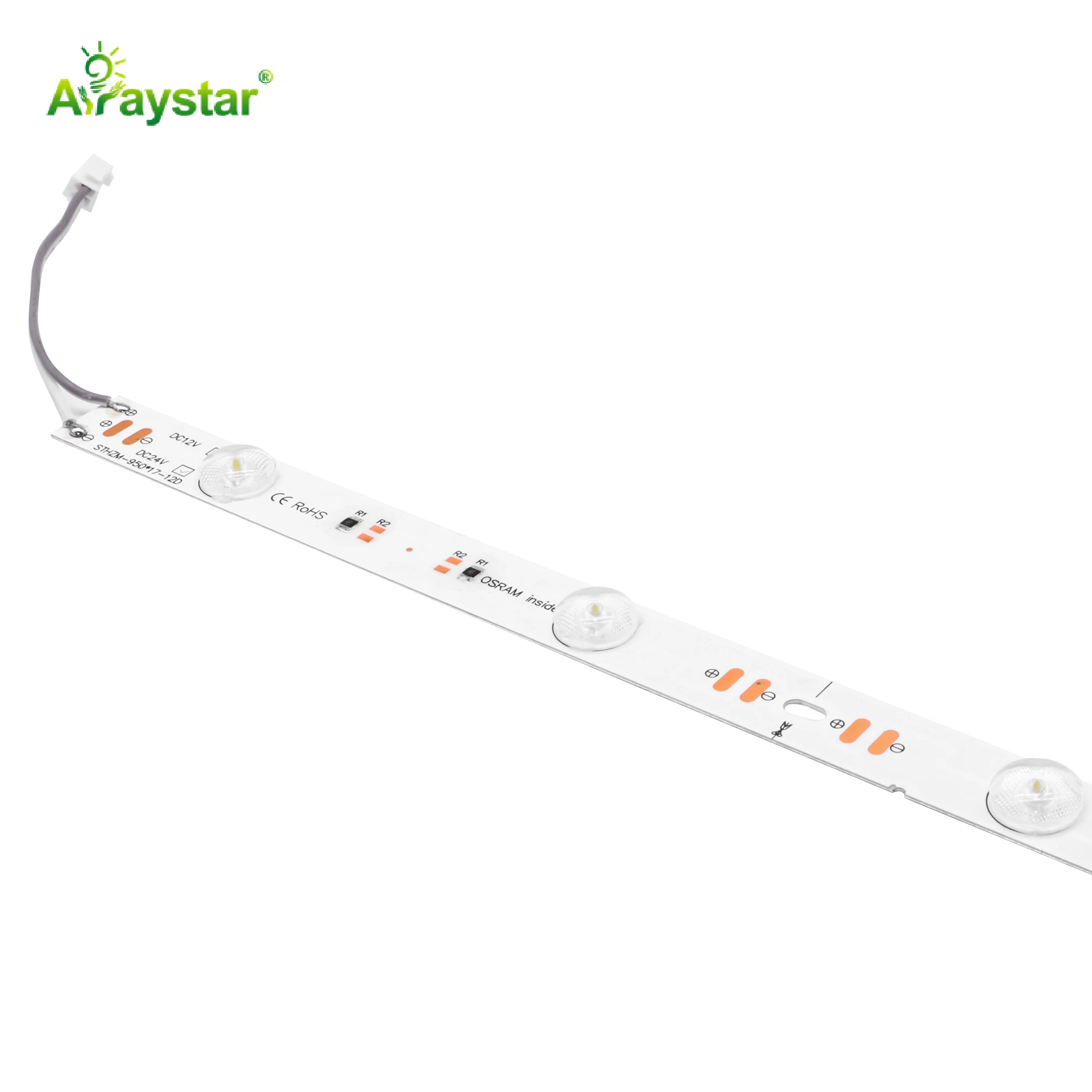
The cleanest fix on long shelf runs is not to chain the bars at all. I feed 24 V into the midpoint of the run and let the bars draw from both directions. With power in the centre, the voltage drop on each half-run is halved, and the contact at the joins stops being the bottleneck. On a 3 m run that means a second feed wire along the shelf, not a bigger connector.
I also match the bar length to the LED pitch. A 960 mm bar has its end pads spaced to the LED pitch; if you butt a 480 mm bar next to a 960 mm bar, the pad positions do not line up and the connector sits on a copper gap. Use matching-length bars end to end, or bridge manually.
What I spec for a clean long run
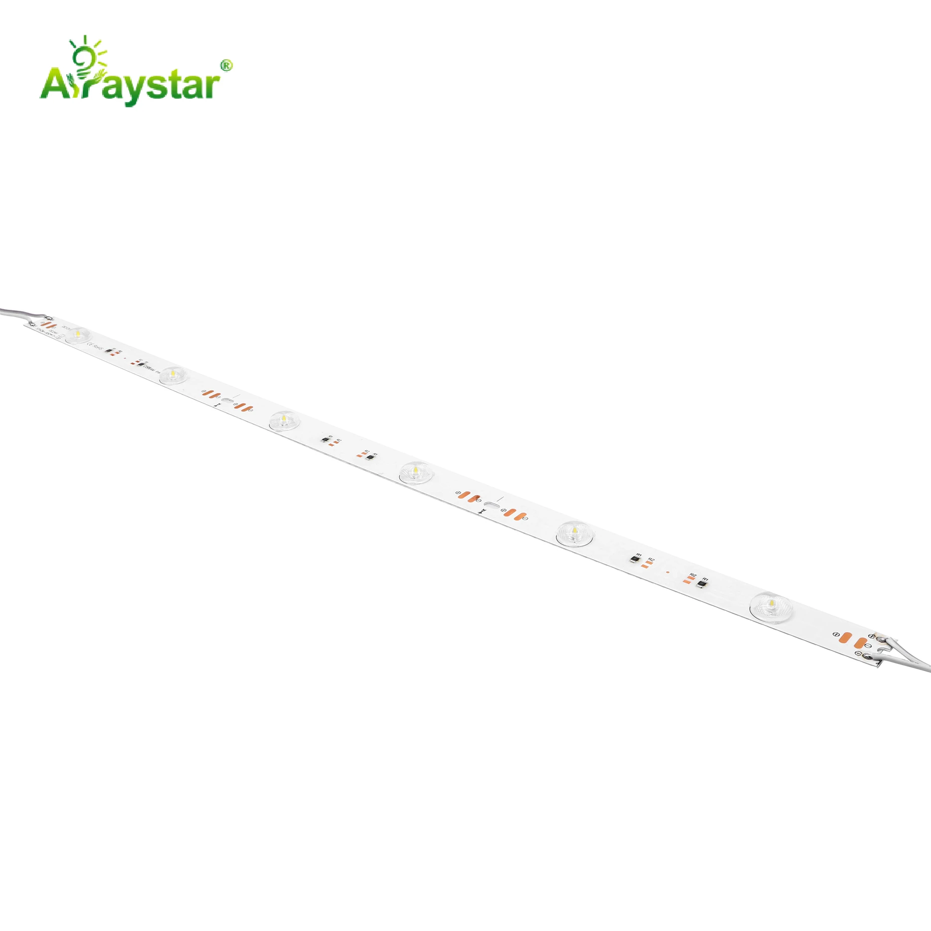
My rule of thumb is one feed per three bars, max. Beyond that I inject again. I also specify 24 V constant-voltage bars with an end-to-end voltage test on the bench before install; if the last LED on a bar drops below 23.5 V at full load, I shorten the run or add a feed. The dim pad you see on the shelf is just the visible symptom of a mis-engineered bus.
If a job already has dark bands, I do not replace bars. I open the join, add a soldered copper bridge between the two end pads, and inject a second feed at the midpoint. That is a ten-minute fix per join, and it usually clears the band without touching a single bar.
Recommended Products
Frequently Asked Questions
Why are joined rigid LED bars dim at the end pad?
The narrow end pad on a rigid bar carries only that bar current by design. Chaining a second bar off it adds contact resistance and another 0.3 to 0.5 V drop, so the LEDs next to the pad run low. It is a bus problem, not a bin problem.
Can I just use longer bars to avoid the join?
Longer bars help only up to the point where their own end voltage drop shows. A 960 mm bar is fine under a single shelf; beyond about 1.5 m total run, even a single long bar starts to dim at its far end. A mid-run feed beats a longer bar.
How often should I inject power on a long rigid-bar run?
Plan on one feed per three bars, roughly every 1.5 to 2 m, on a 24 V constant-voltage run. Inject at the midpoint so current flows both ways. If the last LED on the run reads below 23.5 V at full load, add another feed.
Does a wider copper connector actually remove the dark band?
It removes most of it. A 5.5 mm snap pad drops 0.3 to 0.6 V; a soldered bridge across both end pads drops 0.1 to 0.2 V, which is below what your eye reads. For a fully invisible join, inject a second feed right at the join instead.
Should I mix 480 mm and 960 mm bars end to end?
Avoid it. The end pads are spaced to the LED pitch, and mixing lengths puts the connector on a copper gap rather than a pad. Use matching lengths, or bridge the join manually and add a feed. The visible dark band is usually worse on a mixed-length join.
Need help with your LED project?
Get factory-direct pricing, free samples and engineering support within 24 hours.
Email: info@arraystarled.com | Phone: +86-0755-2103-6746 | WhatsApp: 0086 1581 8514 077
Need to size your power supply? Use our LED Strip Power Calculator to find the right driver in seconds.