The Solder Pad Peeled Off When I Reconnected the Strip - Can It Be Saved?
- 2026-11-02 15:55
- /
- Arraystar LED
You are not heavy-handed. A pad peels when the copper-to-fibreglass bond has already been weakened by two or three hot iron touches, and the fourth one just lifts the whole copper off. I bridge the gap with a thin wire to the nearest surviving pad, and ninety percent of the run keeps working.
What actually peeled off the board
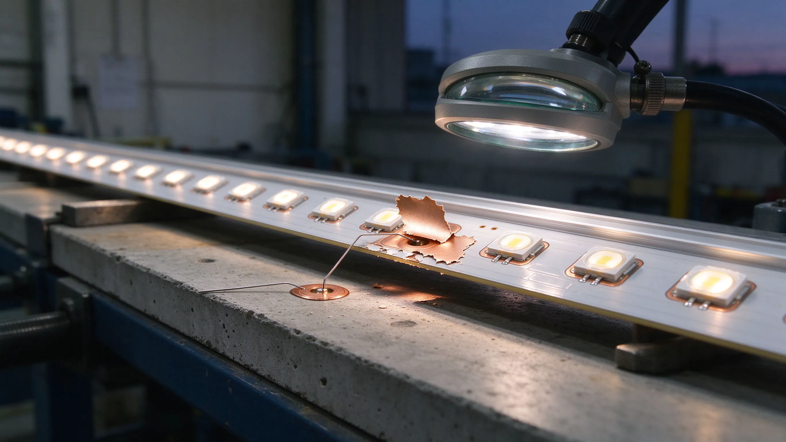
The phone photo almost always shows the same thing: a ragged copper rectangle about 2 by 5 mm still stuck to the solder blob on the wire, while the strip underneath has a pale green or white patch where the foil used to be. Sometimes a thin hair of copper remains, sometimes the whole pad is gone down to the fibreglass weave. Either way, the line that used to feed that LED segment has been cut at its most fragile point.
I see this most on 5 V density strips where the copper foil is only 18 micrometres thick and on narrow 4 and 5 mm PCB widths, where the pads sit close to the board edge. It almost never happens on a first solder. It happens on the third or fourth rework of the same joint, after the pad has already been heated past its glass transition.
Why the bond let go on that particular joint
FR-4 fibreglass and the copper foil are joined by a thin layer of epoxy adhesive that softens around 120 to 130 C. A 30 W iron tip at 350 C sitting on a pad for three seconds pushes the pad copper well past that temperature. The first rework is fine. The second blisters the bond. The third, when you wiggle the joint to see if it is cold, the copper lifts clean off.
The dark bubbled pad is the one that looks okay and dies next month.
| What you see | What it means | What to do |
|---|---|---|
| Pad fully off, bare fibreglass | Copper bond destroyed | Bridge to nearest pad with wire |
| Hair of copper still attached | Partial lift, pad weakened | Re-solder fast, low heat |
| Pad intact but dark / bubbled | Heat-damaged, will fail next time | Scrape, tin, bridge anyway |
The bridge repair, step by step
Tools and heat I use
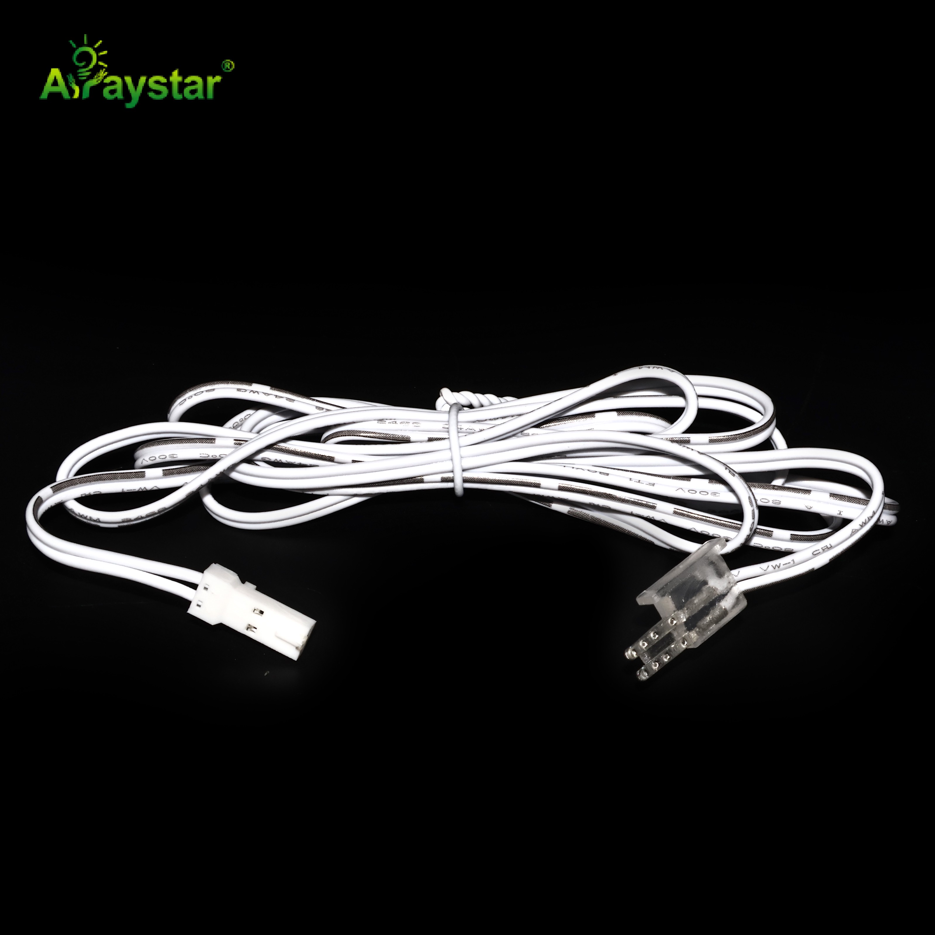
- A 0.3 to 0.5 mm stranded tinned copper wire, stripped to about 8 mm.
- A 25 to 30 W iron with a conical tip, set to 300 C, not 380 C.
- No-clean rosin-core 0.8 mm solder, and a copper braid for cleaning.
I first clean the area with isopropyl alcohol and scrape the lifted pad surround with a fresh craft knife until I see bright fibreglass and the nearest intact pad. Then I tin the surviving pad, tin one end of the bridge wire, and solder the wire down on that pad in under two seconds. From there I run the wire across the damaged zone to the component or trace on the far side, which is usually the anode pad of the first LED in the dead section. The wire itself carries the current; the lifted pad is gone for good.
When the section is truly lost
If the lifted pad sits at the data or power injection point and the trace on both sides has also lifted, bridging gets messy. On a 5 V digital strip, the first LED after the data pad is the whole problem: if its die or its decoupling pin has been damaged by the heat, every pixel after it stays dark no matter how cleanly you bridge.
My rule of thumb: if the dead zone is one LED on a digital strip, or one cut-section on a monochrome strip, and the lifted pad is at the cut line, I just cut 50 mm back to the next intact section and reconnect there with a solder-free latch. Trying to rescue 10 mm of PCB costs more time than it is worth. On a single-colour 12 V strip, you can also jump over the dead segment entirely by feeding 12 V into the next cut pad downstream.
How to stop the next pad lifting
The single biggest change I made was stopping the wiggle test. People press and tug a joint after soldering to see if it is solid; on a hot pad that tug is exactly what lifts the copper. I let the joint cool for ten seconds, then I nudge it with tweezers, not with my fingernail. I also drop the iron temperature to 300 C and keep contact under three seconds. A wet sponge to clean the tip before, not during, the joint.
- Use a solder-free latch on repeated connectors; every iron touch is a chance to lift a pad.
- Tin the wire first, then the pad, so the joint takes less than two seconds of heat.
- If a pad has already been reworked twice, stop and cut back to a fresh section.
- On 4 mm and 5 mm strips, support the board behind the joint so flex does not crack the copper.
Recommended Products
Frequently Asked Questions
Can a lifted solder pad on an LED strip be fixed at all?
Yes, most of the time. Scrape the area clean, tin the nearest surviving pad, and run a 0.3 to 0.5 mm tinned wire from that pad across the lifted zone to the trace or component on the other side. Keep iron contact under two seconds at 300 C. If the trace on both sides is also lifted, cut 50 mm back and restart.
What temperature should my iron be for LED strip pads?
300 C, not the 380 C people default to. The copper foil on a flexible strip is 18 micrometres thick and the epoxy bond softens near 120 to 130 C. A hotter iron sounds faster but you spend the same three seconds fighting a wet joint and you lift the pad. Pre-tin the wire so the joint flows in under two seconds.
How do I know if the LED itself is dead, not just the pad?
Bridge the pad, power the run, and watch the first LED in the dead zone. If it lights, the pad was the only fault. If it stays dark but the next LED in line lights when you jump data past it, the first LED die is damaged. On a digital strip you can cut that one pixel out and jumper its data line straight through.
Should I use solder-free connectors instead of iron to protect pads?
For repeated disconnects, yes. A latch connector presses the phosphor-plated contact onto the pad with no heat at all, so the pad survives dozens of connects. Solder-free parts work best on clean, straight cut pads. If the pad is already lifting, the latch will not rescue it, but it will stop the next joint from suffering the same fate.
How thick is the copper on LED strip PCB, and why does that matter?
Most flexible strips use 18 micrometre, which is half an ounce, copper foil. That is thin enough to bend, but it also peels at low temperature. Rigid FR-4 boards use 35 micrometre one-ounce copper, which takes far more heat abuse. When you rework a flexible strip, treat it like thin tape, not like a PCB.
Need help with your LED project?
Get factory-direct pricing, free samples and engineering support within 24 hours.
Email: info@arraystarled.com | Phone: +86-0755-2103-6746 | WhatsApp: 0086 1581 8514 077
Need to size your power supply? Use our LED Strip Power Calculator to find the right driver in seconds.