LED Strip Polarity & Wire Color Code Explained
- 2026-09-18 18:18
- /
- Arraystar
Quick Answer
On LED strip DC wiring, red is positive (+) and black (or white) is negative (−). Always match the strip’s printed + and − markings and arrows, feed power at the marked input end, and never swap them — reverse polarity will not light the strip and can damage it. When in doubt, test with a multimeter before connecting.
📑 Table of Contents
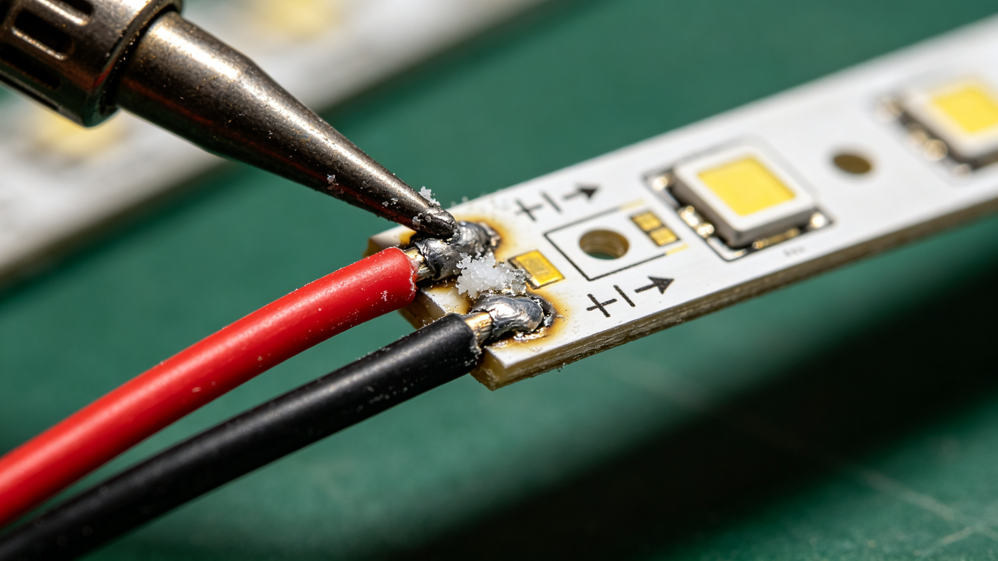
Red to +, black to − — the whole installation lives or dies on getting polarity right.
LED Strip Polarity: What It Means
LEDs are diodes: they only conduct — and light — when voltage is applied in the correct direction. On a flexible strip, the LEDs are wired in groups with a defined current path, so the strip has a clear positive (+) input end and a negative (−) return. Apply the supply the right way round and every LED lights; swap them and nothing happens — or, on unprotected strips, something gets damaged. Polarity is the first thing to check whenever a strip “just won’t turn on”.
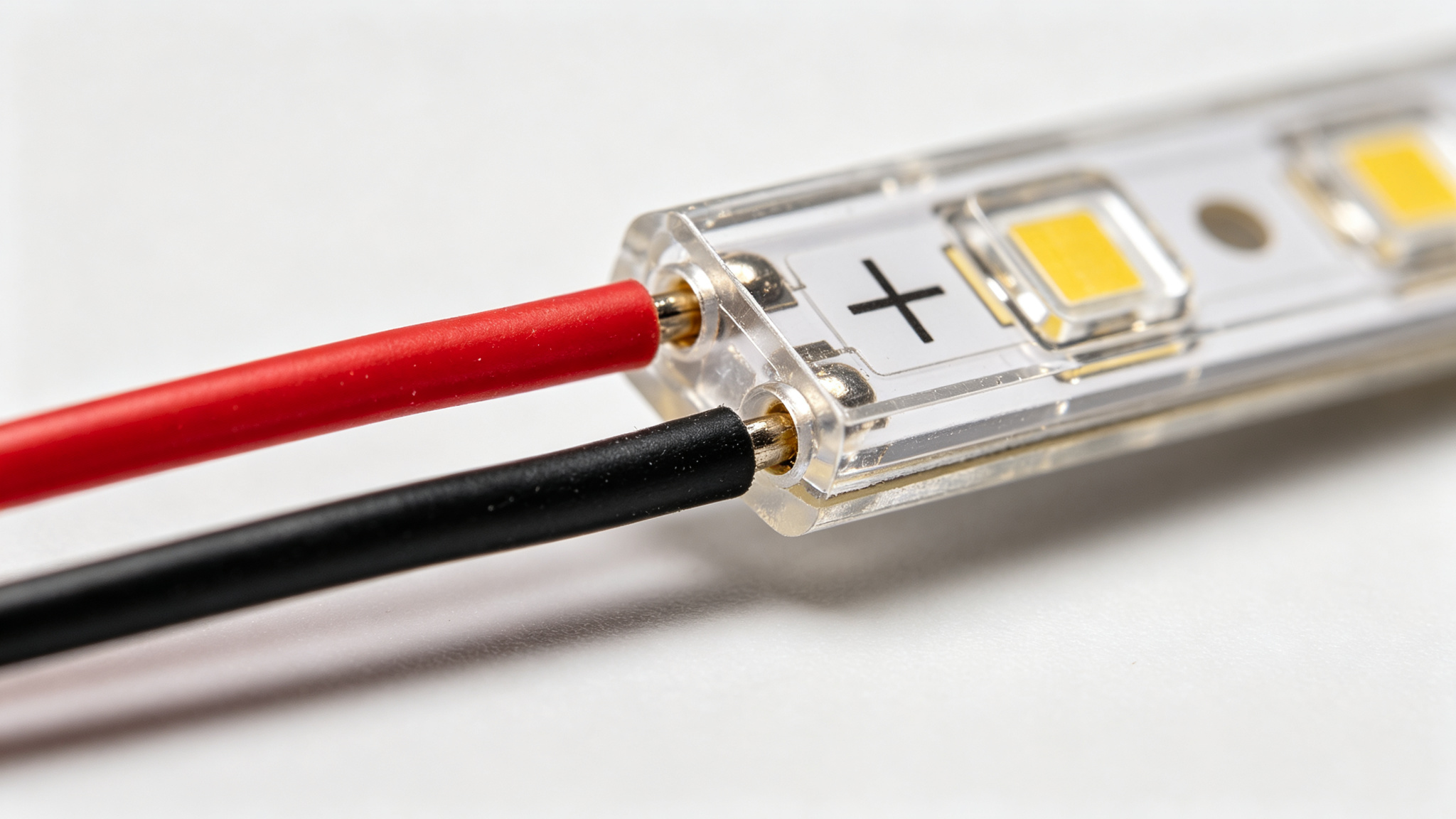
The clear + and − legend on the PCB is your ground truth — trust it over assumptions about wire color.
Wire Color Codes: the Common Standard
Most LED strip manufacturers follow a near-universal DC color code, but always confirm against the product datasheet and the PCB markings:
| Wire Color | Role (Single Color) | RGB / RGBW Role |
|---|---|---|
| Red | Positive (+) | Red channel |
| Black / White | Negative (−) | Common +12V/+24V (common anode) |
| Green | — | Green channel |
| Blue | — | Blue channel |
| White | — | White channel (RGBW) |
Note the trap: on common-anode RGB strips, black is often the positive supply, not the negative — so never assume. The PCB labels and the datasheet decide. For multi-channel wiring and control, see the control comparison.
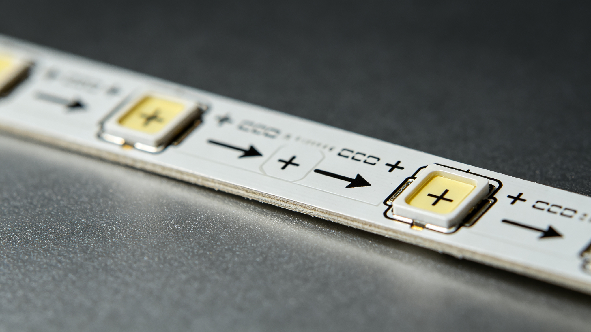
Arrows show the direction of current; feed at the start arrow, where + and − are marked.
Reading Markings on the Strip PCB
Look for three things near the cut line: a + and − symbol, small arrows showing current direction, and the voltage marking (12V/24V). Power should enter at the input end where the arrows point away. Most strips are bidirectional electrically (you can feed from either end of a short run), but injecting at the marked input keeps everything predictable — especially on long runs, which is where our voltage drop guide applies.
Rule of thumb: red = +, black = − on single-color strips, but always confirm against the PCB’s printed +/− and the datasheet before powering up.
What Happens If You Reverse Polarity
Most modern strips and drivers have some reverse protection, but do not rely on it. Without protection, reversing polarity simply stops the LEDs lighting; with marginal circuits it can blow the onboard resistors or damage chips. On RGB controllers, swapped channels produce the wrong colors rather than no light — a classic “why is blue showing when I ask for red” fault. The safe move: verify polarity with a multimeter before the first power-up.
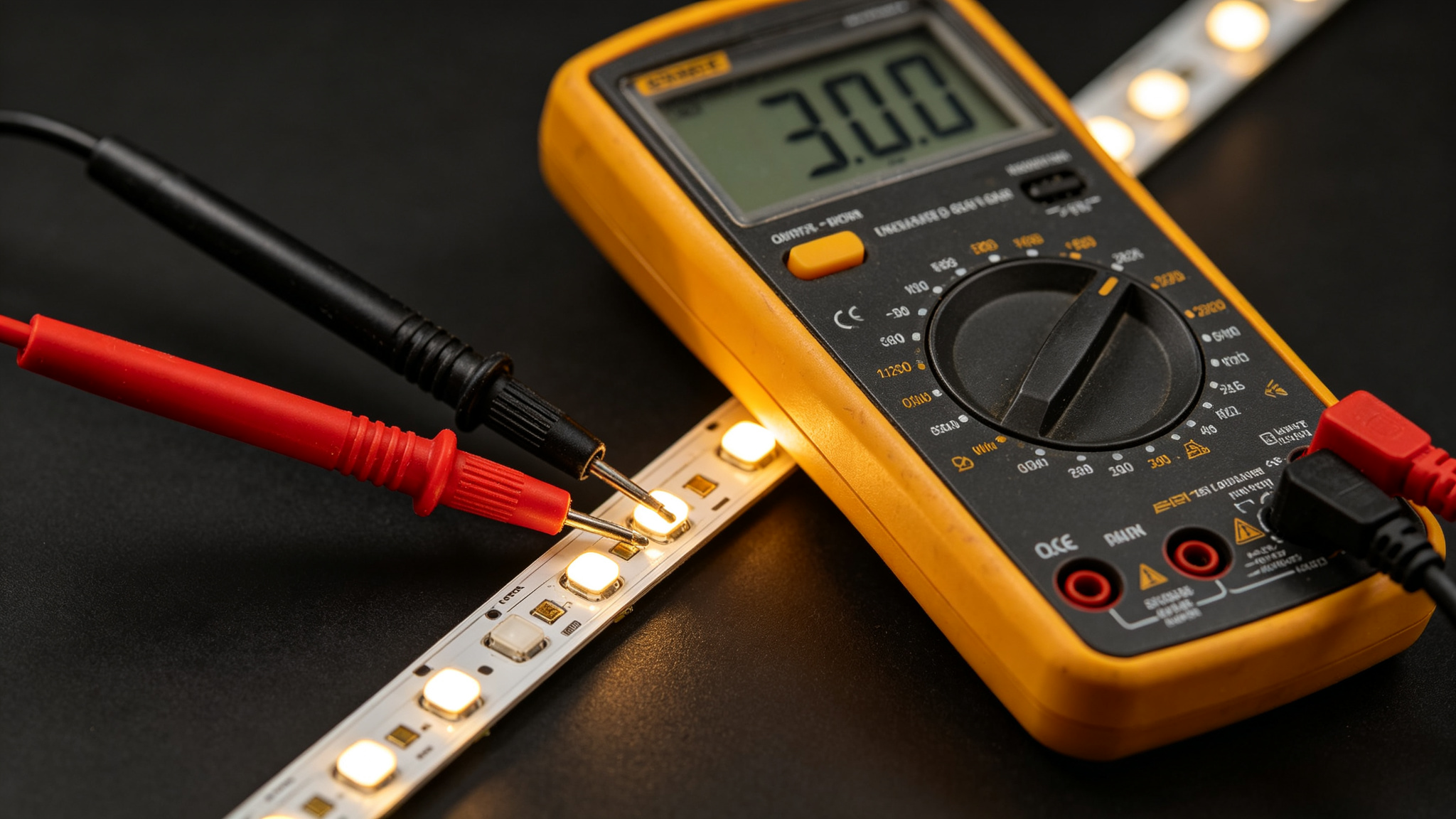
A quick meter check of the supply output removes all guesswork before the strip is connected.
Correct Connection Procedure
- Identify + and − on the PCB and on your power supply output terminals.
- Match colors (red to +, black to −) and verify against the markings.
- Solder or clip cleanly, keeping joints short and insulated — see the soldering tutorial.
- Double-check with a multimeter before applying load; then power on briefly.
- For solder-free connectors, align the strip contacts with the correct +/− slots.

A clean solder joint on the correct pads beats a taped guess every time.
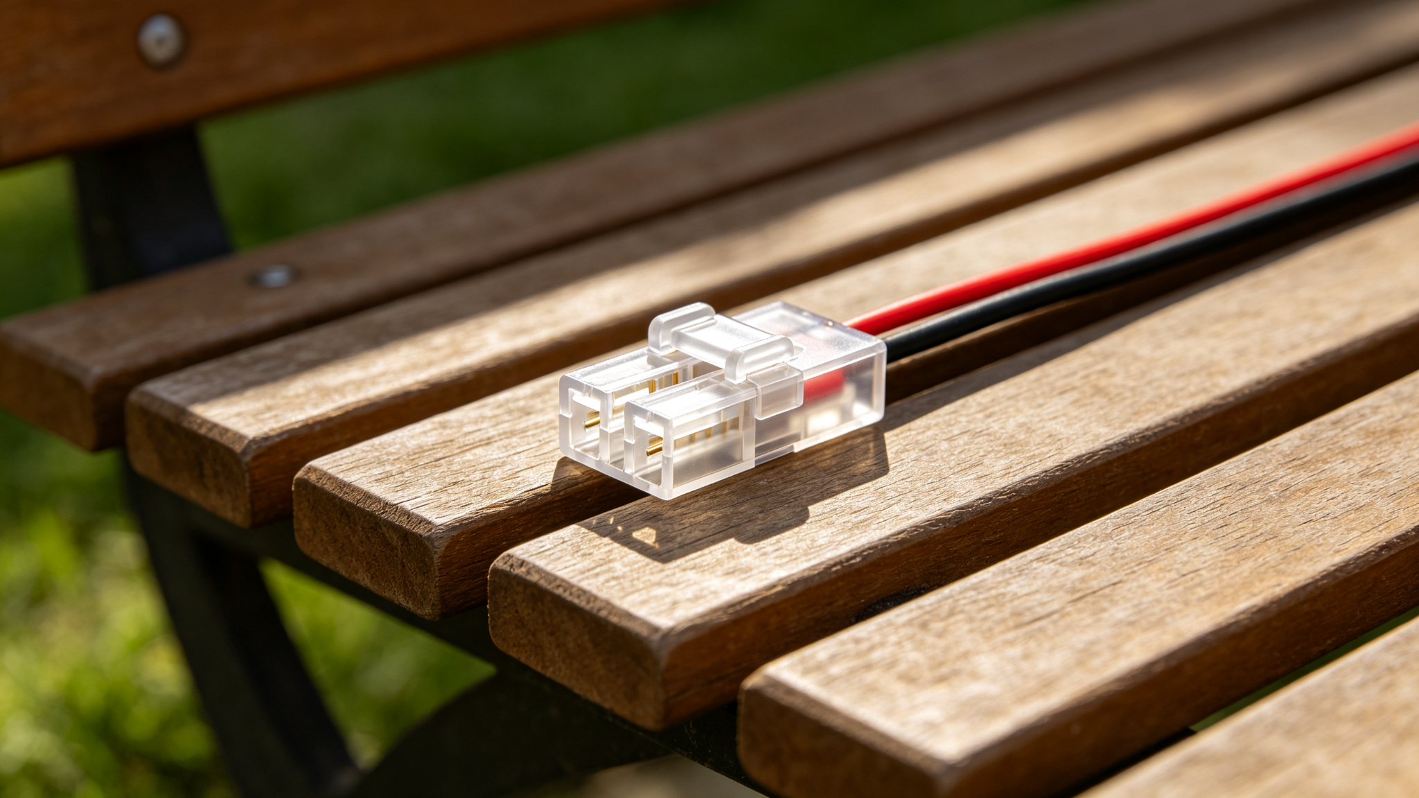
Solder-free connectors label their +/− slots — line the strip up correctly and latch.
Recommended Products


Frequently Asked Questions
What happens if I wire LED strip backwards?
LEDs only light in the correct direction, so a reversed strip simply will not turn on. On unprotected circuits it can also damage onboard resistors or chips. Always match red to + and black to −, and confirm against the PCB’s printed markings.
Is red always positive on LED strip wires?
On single-color DC strips, red is almost always positive and black or white is negative. But RGB common-anode strips often use black as the positive supply, so never rely on color alone — check the PCB labels and datasheet.
Does LED strip polarity matter for RGB controllers?
Yes. Swapped or mis-labeled channels produce wrong colors (blue shows when you ask for red, and so on). Match each channel wire to its controller terminal exactly, and confirm the common is +12V/+24V or − as the controller requires.
Can I cut and re-join LED strip polarity the wrong way?
No — every joint must preserve + to + and − to −. If you flip a segment 180° physically, its electrical direction stays the same; keep the current direction consistent along the run. Use connectors or solder that follow the PCB markings.
Need polarized connectors or wiring diagrams?
Get factory-direct connector selection and a custom quote within 24 hours.
Get a Quote