Solderless LED Strip Connectors: How I Use Quick-Connect Terminals With Zero Solder
- 2026-10-08 18:23
- /
- Arraystar LED
A solderless clip is not a worse version of a solder joint — it is a different tool. Picked for the right width and pin count, seated all the way to the stop, pull-tested, and kept under its amp rating, a quick-connect terminal is how I finish serviceable retail and under-cabinet jobs in a fraction of the time with zero callbacks. This is exactly how I select and install them, including the three or four things that make a no-solder joint fail.
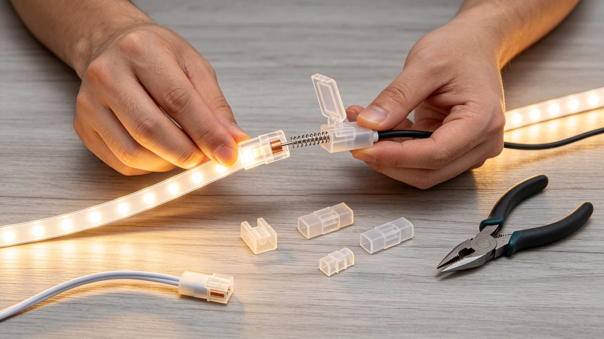
What a solderless quick-connect terminal actually is
If you opened my site kit you would find more clear plastic clips than controllers. The little hinged solderless connector is the part that lets me land a driver lead onto a strip, or join two reels end to end, without heating an iron, stripping tiny wires, or risking a burnt pad on a cheap reel. I grab one almost every job, and most of the "these connectors are garbage" posts I see online trace back to a clip that was picked or installed wrong, not a part that is fundamentally bad.
Under the clear housing it is a simple machine. A row of spring-loaded contacts (or piercing teeth on some IP-rated versions) sits directly over the strip's copper pads. When you close the hinged cover, those contacts are pressed down onto the copper with real force, and that mechanical pressure is the electrical connection. A soldered joint is a metallurgical bond — the tin alloys to the pad and the wire and you get a near-zero-resistance, permanent join. A clip is a pressure contact: still low resistance when it is clean and fully seated, but removable, and only as good as the spring force and the contact area holding it there.
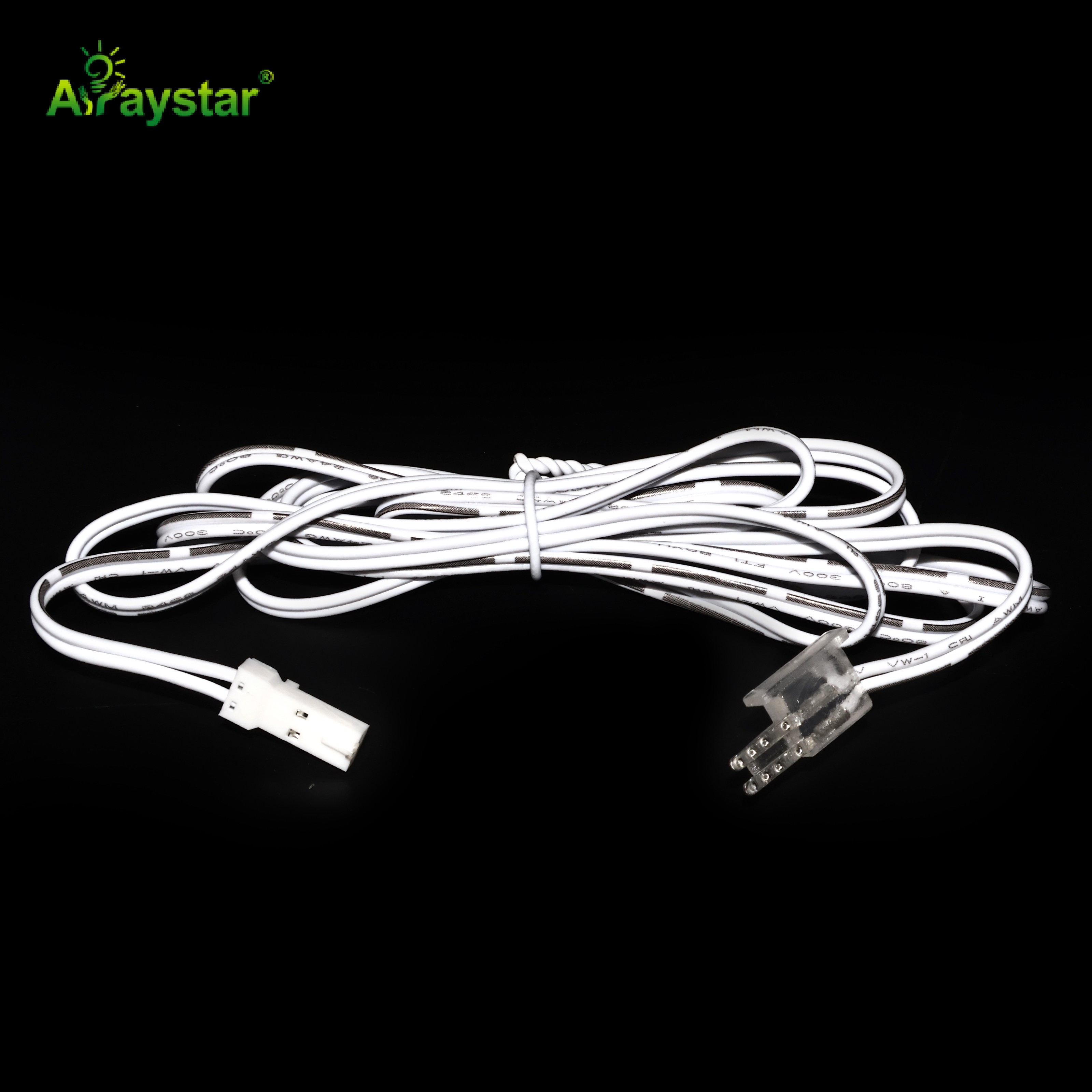
The parts inside the clip
- A clear polycarbonate body so I can actually see the pads line up before I commit.
- A hinged or sliding cover that drives the contacts down when it locks.
- Tinned or gold-flashed spring pins / piercing teeth, one per pad (two for single color, four for RGB, five for RGBW).
- Moulded locating posts or ribs that key the strip to the correct width and polarity.
- On waterproof versions, a silicone gasket or sealing end-cap — that is the part that keeps water out, not the plastic itself.
The naming tells you the size: a 0408 clip is built around the 4mm / 8mm narrow-strip family, while a 0508 covers the wider 5mm and 8mm boards. Get the width and the pin count right and half the battle is already won.
The connector families I actually stock
I do not buy one bag and force it onto every strip. There are five families on my shelf, each for a specific geometry, and using the wrong one is the fastest way to a flickering joint.
The five solderless connector families and the job each one is actually built for.
| Connector family | Fits | Where I use it | Watch-out |
|---|---|---|---|
| Wire-to-strip pigtail | 4/5/8/10/12mm, 2/4/5-pin | Driver lead to the first strip; power-injection taps | Pin count must match the pads |
| Strip-to-strip coupler | Same width, same pin count | Joining two reels end to end | Mind polarity and the cut gap |
| Corner / L / T piece | Same series, gapless | 90-degree turns inside an aluminum channel | Adds a few millimetres — check the channel |
| Neon / extrusion cap | 6x12, 8x16, 10x10 top- or side-bend | Feeding and joining square neon flex | Match cross-section and bend direction |
| Waterproof gland / end-cap | IP65/67/68 runs | Outdoor and damp locations | Seal the cable entry, not just the strip |
Single-color strips are two contacts (positive and the shared negative). RGB is four, RGBW is five, and addressable pixel strip adds a data line — a 2-pin clip will never carry a 5-pin RGBW run, no matter how hard you squeeze it. When I am unsure, I count the copper pads on the cut line and match that number to the clip before I open the bag.
Installing a clip-on connector, step by step (the way that avoids callbacks)
This is the whole job. Done like this the joint is mechanically solid and reads almost like a solder pad on the meter; rush any step and you get the intermittent, warm, flickers-after-three-days mess that gives clips a bad name.
- 1) Cut straight across the copper pads with the cut mark centered. A diagonal slice leaves one spring pin hanging off the edge of its pad with nothing to bite.
- 2) Open the hinged cover fully and note which side the contacts sit on so the strip goes in the right way up.
- 3) Peel back about 8-10mm of the 3M adhesive — and the silicone skin on an IP-rated strip — so the bare copper lies flat on the contacts instead of resting on top of tape or rubber.
- 4) Slide the strip in until the pads hit the internal stop. The +12/24V mark and the R/G/B or polarity marks must line up with the pins.
- 5) Press the cover down with even thumb pressure until it clicks. On stiff waterproof clips I use the flat handle of my pliers, never a fingernail.
- 6) Give the strip and the wire a firm pull test. If either slides out, open it and redo it on the spot — never just hope it holds.
- 7) Before powering up, meter positive to each color pad and to negative for a short. Ten seconds here saves a controller.
Watch me seat and pull-test the connector in the full demo on YouTube.
The short clip above walks through that exact sequence on the bench — watch the moment I push the strip all the way to the stop and the two tugs I give it afterward. That pull test is the difference between a connector I trust behind a cabinet and one I will be driving back to fix. You can also watch it directly on YouTube here: https://youtu.be/azLk0s5DKeQ
Why a no-solder joint fails — and what I do about it
When a clip lets go there is usually a specific, repeatable reason. These are the ones I run into on site and how I head them off.
- Not seated to the stop (the most common). A pin resting on the edge of a pad makes partial contact — it works, gets warm, oxidizes, then drops out. Fix: push until the copper meets the internal stop and you can see full pad coverage through the clear body.
- Coating or oxidation on the pads. Some silicone-extruded strips leave a thin skin or conformal coat over the copper that flat spring pins cannot bite through. Fix: lightly scrape the pad with the back of a knife blade, or specify a clip with sharp piercing teeth.
- Wrong width or pin count. An 8mm clip forced onto a 10mm board sits off-center and only reaches half the pads. Fix: match the model number; this is why I carry both the 0408 and 0508.
- Too much current through one clip. The contact area is small, so at high current it heats, the plastic softens, the spring relaxes, and it gets looser and hotter in a loop. Fix: never feed a whole long run through one coupler — inject power in parallel and let each joint carry only its local section.
- Water wicking in through the cable entry. A waterproof strip with an unsealed connector still floods, because water follows the wire. Fix: pot the end-cap or use heat-shrink with adhesive over the cable gland.
- Thermal cycling and vibration. Outdoor signs and anything on a moving structure flex the joint until the pressure contact opens. Fix: those permanent, hard-to-reach spots get soldered; clips go where I can get back to them.
Solderless vs soldering: where each one actually wins
I am not religious about this. Both belong on the truck, and pretending one is always right is how you end up either melting pads in a customer's window or chasing a dead joint inside a wall a year later. Here is how I actually split it.
My rule of thumb for choosing a clip versus an iron on real jobs.
| Situation | I reach for | Why |
|---|---|---|
| Under-cabinet or retail displays that get re-laid | Solderless clip | Open it and move the run in 30 seconds |
| Site work with no bench, tight schedule | Solderless clip | No iron heat-up, no burn or fire risk in a finished space |
| Mock-ups and prototyping | Solderless clip | Reposition freely until the layout is final |
| High-current feed or power-injection point | Solder | Lowest contact resistance, runs cool for good |
| Permanent outdoor / pool-adjacent / vibrating sign | Solder + potting | Survives years of temperature cycling |
| Neon fixed behind walls vs serviceable cove | Rated cap vs solder+glue | Whichever matches future access |
So the short version: visible, serviceable, low-current-density runs get clips; anything buried in a wall, exposed to weather, or carrying more than roughly 4-5A through a single node gets soldered and sealed. A retail window that changes every season is the perfect clip job. A rooftop sign you will never open again is not.
Amp ratings, wire gauge and voltage drop at the connector
Treat the clip as a small extra resistance sitting in series with your strip. Even a few tens of milliohms at several amps produces real I-squared-R heat and a visible voltage drop, so I size around the connector instead of pretending it is invisible.
- Read the per-contact amp rating on the clip and derate it 30-40% when the joint lives inside a closed aluminum channel, where the heat cannot convect away.
- Never daisy-chain a full-load run through one coupler. Inject power in parallel roughly every 5m on 12V and every 10m on 24V so each connector only feeds the strip next to it.
- Match the pigtail gauge to the load. Short 22/20AWG tails are fine for local feeds; a long 10A feed on thin 24AWG lead will brown out the strip before the clip ever reaches its limit.
- On 12V, a 0.2V loss shows up as color shift toward one end. The extra headroom of 24V is one reason I default to 24V on long, connector-heavy layouts.
If you are unsure whether a driver has enough watts for the strip plus everything attached to it, our LED strip power calculator sizes the driver in a few seconds, and it is worth running before you commit to how many injection points and connectors a long run actually needs.
Recommended Products
Frequently Asked Questions
Do solderless LED strip connectors actually work, or are they just junk?
They work when they are matched and installed correctly. I have had clip-on joints in serviceable retail and under-cabinet installs running for years without a callback. The reliable ones share four traits: the exact width and pin count for the strip, the strip seated all the way to the internal stop, a firm pull test after closing, and a load kept under the clip's amp rating. Most failures are a wrong-size clip, a pad not pushed home, or water entering at the cable entry rather than the connector design itself.
Why does my LED strip not work after I clicked the connector on?
Walk it in order: confirm the cut runs straight across the center of the copper pads, that the strip is pushed fully in until it hits the stop, and that the polarity and R/G/B marks line up with the pins. On IP-rated strips, check that a silicone skin or leftover 3M tape is not sitting between the contacts and the copper. Make sure the cover clicked shut, then meter for continuity and for a short between positive and each color before powering up. In practice a strip not seated to the stop and reversed polarity are the two causes I find most.
Can I use solderless connectors on waterproof IP67 LED strips outdoors?
Yes, but use the waterproof version with a silicone gasket or a purpose-made sealing cap (square neon needs its own matched cap), and treat the cable entry as the real weak point. A sealed strip can still flood if water travels down the wire into an unsealed connector, so I pot the end-cap or apply adhesive-lined heat-shrink over the gland. For permanent outdoor or pool-adjacent joints that I cannot reach later, I solder and pot instead and keep clips for accessible sections.
How many amps can one solderless LED strip connector handle?
It depends on the contact rating of the specific clip; smaller hinged connectors are typically in the low single-digit-amp range per contact, and you should derate that further inside an enclosed aluminum channel where heat builds. Rather than pushing one coupler to its limit on a long run, inject power in parallel so each connector only carries its local segment, and step the pigtail wire gauge up on main feeds. For a permanent feed above roughly 4-5A at one node I solder, because the lower contact resistance runs noticeably cooler.
Can I join different-width strips, or single-color to RGB, with one clip?
Not directly. Different widths have different pad spacing, and single-color (2-pin), RGB (4-pin) and RGBW (5-pin) strips have different contact counts and electrical definitions, so a single clip cannot bridge them. To change width, use the correct clip on each side joined by a short flying lead; single-color and RGB sections can only meet at the controller or power side on their matching channels, never through one solderless connector.
Need help choosing the right solderless connector?
Tell us your strip width, pin count and IP rating and we will ship the matching quick-connect terminals with free samples.
Email: info@arraystarled.com | Phone: +86-0755-2103-6746 | WhatsApp: 0086 1581 8514 077
Need to size your power supply? Use our LED Strip Power Calculator to find the right driver in seconds.